Method for weaving pile fabrics and pile fabric woven with such a method
a technology of pile fabric and weaving method, which is applied in the field of weaving pile fabric and weaving pile fabric with such a method, can solve the problems of not being ideal in terms of esthetics and not completely smooth pile fabri
- Summary
- Abstract
- Description
- Claims
- Application Information
AI Technical Summary
Benefits of technology
Problems solved by technology
Method used
Image
Examples
second embodiment
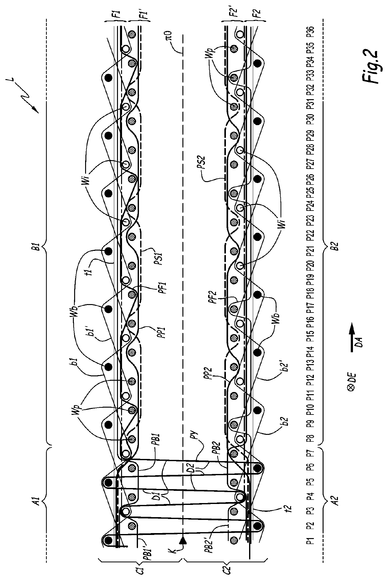
[0108]In the second embodiment, shown in FIG. 2, the wefts Wi, Wb and Wp are inserted in successive series of four picks. At a first P1, P5, P9, . . . of a series of four picks, one back weft Wb is inserted in the top shed and one patterning weft Wp is inserted into the bottom shed. At a second pick P2, P6, P10, . . . of the same series of picks, one back weft Wb is inserted into the bottom shed and one patterning weft Wp is inserted into the top shed. At a third pick P3, P7, P11, . . . of the same series of picks, one inner weft Wi is inserted into the top shed and one patterning weft Wp is inserted into the bottom shed. At the fourth pick P4, P8, P12, . . . of the same series of picks, one inner weft Wi is inserted into the bottom shed and one patterning weft Wp is inserted into the top shed.
[0109]As can be derived from FIG. 2, the position of each pile thread PY, PB1, PB1′, . . . at picks P1 to P36 varies between a top position, a middle position and a bottom position, with an ap...
third embodiment
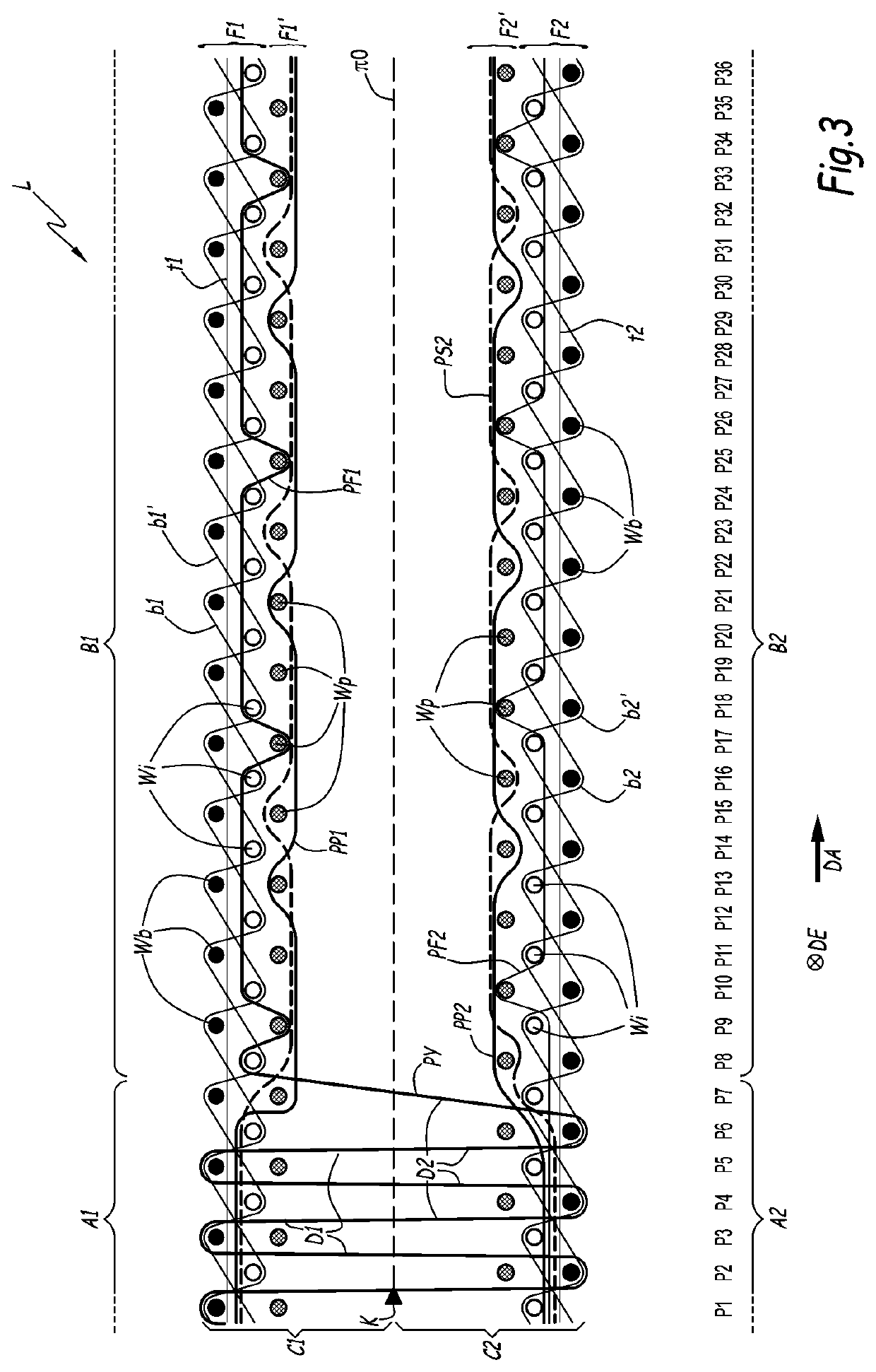
[0113]In the invention represented in FIG. 3, the method is implemented on a face-to-face weaving machine with three weft insertion means, e.g. three rapiers.
[0114]Wefts are inserted in successive series of two picks. At a first pick P1, P3, P5, . . . of a series of two picks, one back weft Wb is inserted into the top shed, one patterning weft Wp is inserted into the middle shed and one inner weft Wi is inserted into the bottom shed. Both the back weft Wb and the patterning weft Wp inserted at such a pick are incorporated in the top carpet C1. The inner weft Wi is incorporated into the bottom carpet C2. At a second pick P2, P4, P6, . . . of the same series of picks, one back weft Wb is inserted into the bottom shed, one patterning weft Wp is inserted into the middle shed and one inner weft Wi is inserted into the top shed. Both the back weft Wb and the patterning weft Wp inserted at such a pick are incorporated into the bottom carpet C2. The inner weft Wi is incorporated in the top ...
fourth embodiment
[0117]In the fourth embodiment shown in FIGS. 4 and 5, the method is implemented on a face-to-face weaving machine with two insertion means, e.g. two rapiers.
[0118]Patterning wefts Wp are divided into two different types of patterning wefts, namely a first type of patterning weft Wpa and a second type of patterning weft Wpb. For instance, the two types of patterning wefts may correspond to different colors of patterning wefts.
[0119]Alternatively, the two types of patterning wefts are made of different materials.
[0120]The wefts Wi, Wb, Wpa and Wpb are inserted in successive series of four picks. At a first pick P1, P5, . . . of a series of four picks, one patterning weft Wpa of a first type is inserted into the top shed and one inner weft Wi is inserted into the bottom shed. At a second pick P2, P6, . . . of the same series of picks, one patterning weft Wpb of a second type is inserted into the top shed and one back weft Wb is inserted into the bottom shed. At a third pick P3, P7, . ...
PUM
| Property | Measurement | Unit |
|---|---|---|
| area | aaaaa | aaaaa |
| tension | aaaaa | aaaaa |
| structures | aaaaa | aaaaa |
Abstract
Description
Claims
Application Information
 - R&D
- Intellectual Property
- Life Sciences
- Materials
- Tech Scout
- Unparalleled Data Quality
- Higher Quality Content
- 60% Fewer Hallucinations
Browse by: Latest US Patents, China's latest patents, Technical Efficacy Thesaurus, Application Domain, Technology Topic, Popular Technical Reports.
© 2025 PatSnap. All rights reserved.Legal|Privacy policy|Modern Slavery Act Transparency Statement|Sitemap|About US| Contact US: help@patsnap.com


