Weighting system for putter type golf club

a golf club and putter technology, applied in the field of golf putters, can solve the problems of greatly diminished feel of golfers, and achieve the effect of more control of the putter

Active Publication Date: 2021-08-24
DIEPENBROCK WILLIAM R
View PDF12 Cites 0 Cited by
  • Summary
  • Abstract
  • Description
  • Claims
  • Application Information

AI Technical Summary

Benefits of technology

[0004]The putter of the present invention is radically different from putters that are currently available in the marketplace that use hollow shafts. The putter of the present invention uses a solid steel shaft having a diameter of ¼ inch extending between a blade putter head that is lighter than conventional putter heads of similar shape and an upper butt end of the golf club. The putter head weighs less than the weight of most conventional putter heads that typically weigh between 335 and 370 grams. The shaft weighs at least and preferably more than twice the weight of conventional putter shafts that typically weigh approximately 100 grams. The weighting system of the putter includes an upper weighted, cylindrical adapter at the upper end of the small diameter, steel shaft. The weight system positions the balance point of the putter significantly higher toward the upper butt end of the putter closer to the golfer's hands. This balance point location allows the golfer to have more control of the putter during the execution of a putting stroke.
[0005]A conventional slip-on golf grip is attached to the upper butt end of the putter using the upper weighted adapter as a support for the grip to complete the structure of the putter. The length of the weighted adapter is at least the same size as the length of a conventional grip and preferably slightly longer and having at least a length of 11 inches, the size of most conventional golf grips. The adapter is formed with an internal bore of approximately ¼ inch along the entire length thereof in order that it snugly fits over the ¼ inch shaft when the putter is assembled. The weight of the adapter is slightly less than half the weight of the shaft, preferably approximately 40% of the shaft weight. In combination with the weight of the grip, the weighted adapter locates a longitudinal balance point of the putter from a normal distance approximately 35% of the length of the putter from the putter head toward the butt end of the club to an improved location approximately 60% of the length of the putter from the putter head. The higher balance point on the shaft of the putter closer to the golfer's hands allows the golfer to have more control of the putting stroke as compared with putters that have a balance point lower toward the putter head.
[0007]Typically the weighted, cylindrical adapter is a milled aluminum cylinder measuring at least 11 inches in length with a fixed tip reducer on the lower end that tapers down toward the diameter of the ¼ inch shaft. The weighted adapter has a central bore approximately ¼ inch in diameter in order to fit over the ¼ inch steel shaft when the adapter is assembled, preferably using a double sided adhesive tape or other adhesive material. The outer circumference of the weighted adapter is sized to fit into the axial opening of a conventional, slip-on golf grip to complete the structure of the putter. The additional weight of the adapter at the upper end of the shaft of the putter, along with the grip, locates the balance point upwardly closer to the golfer's hands as described above.
[0008]The putter shaft with a solid steel core and the weight distribution of the components of the putter result in the head feeling lighter with more feel and reduces vibration and torque when the golf ball is not hit in the exact center of percussion of the striking face. The increased weight of the solid rod all the way to the upper end of the putter and the additional weight of the weighted adapter that typically is under a golfer's hands, in combination with a putter head weight lighter than the majority of conventional putters, moves the balance point closer to the golfer's hands creating more control that, in turn, makes it easier for a golfer to keep the club head on line during a putting stroke.
[0010]Among the objects of the present invention is the provision of a putter type golf club formed of a solid and rigid shaft structure and upper weighted adapter that is balanced to promote stability and feel in a golfer's hands when executing a putting stroke.
[0012]Still another object of the present invention is the provision of a putter type golf club having reduced vibration during the strike of a golf ball and a more solid feel providing feedback to the golfer striking a golf ball during a normal putting stroke.

Problems solved by technology

This is particularly true with older golfers whose physical abilities have declined with age with the result that the golfer's feel is greatly diminished.

Method used


Image

  • Weighting system for putter type golf club

Examples


Embodiment Construction

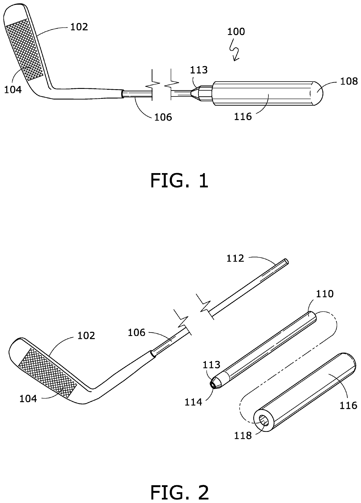
[0016]The drawings show a golf putter 100 of the present invention. The putter has four main parts, a conventional club head 102, with a striking face 104, an elongated shaft 106, an upper weighted, cylindrical adapter 110 and a conventional grip 116. The head 102 and shaft 106 are connected in a conventional way by insertion of the shaft 106 directly into the head 102 or by using a hosel, not shown. Preferably the shaft 106 is generally cylindrical and is made of solid, rigid stainless steel having a ¼ inch diameter extending between the head 102 and an upper end 108 of the putter 100.

[0017]The head 102 may be any shape such as a blade, mallet or similar conventional shape as an example. It will be appreciated the putter head may include separate structures, such as weight members or face inserts, while maintaining a conventional structure.

[0018]The upper weighted, cylindrical adapter 110 has a length of approximately 10-11 inches that extends slightly beyond the end of the golf gr...


PUM


Abstract

A weight system for a putter type golf club that creates a balance point close to a golfer's hands when the putter is used in a normal manner for execution of a putting stroke. The putter is formed of a putter head, an elongated, constant ¼ inch diameter solid metal shaft; and a weighted, cylindrical adapter attached to an upper section of the elongated shaft between an overlying golf grip and the shaft.

Description

RELATED APPLICATIONS[0001]This application is a continuation in part of application Ser. No. 16 / 179,981 filed Nov. 4, 2018 for Putter Type Golf ClubBACKGROUND OF THE INVENTION[0002]The present invention relates to golf putters and in particular to a golf putter having a unique weight assembly for use with a small diameter, solid steel shaft creating enhanced stability during a putting stroke.[0003]When playing the game of golf, it is important and necessary for the golfer to have consistent feel when striking a golf ball in order to produce repeatable golf shots to insure a golf ball travels precise distances and to the desired location. While this is true for all types of golf shots, it is particularly true for golf shots struck with a putter type golf club where the impact force against the golf ball is significantly less than full swing golf shots. Typically, amateur golfers miss hit a golf ball away from the precise center of percussion of a golf putter a large percentage of the...

Claims


Application Information

Patent Timeline
Patent Type & Authority Patents(United States)
IPC IPC(8): A63B53/00A63B60/04A63B60/24
CPCA63B60/04A63B53/007A63B60/24A63B53/14A63B2209/10A63B60/02A63B60/54
Inventor DIEPENBROCK, JR., WILLIAM R.SHEETS, JEFFERY D.
Owner DIEPENBROCK WILLIAM R
Why Eureka
Try Eureka