Capillary force vaporizers

a technology of capillary force and vaporizer, which is applied in the direction of positive displacement liquid engine, steam boiler components, water circulation, etc., can solve the problems that the seal capillary pump of the prior art cannot be readily disassembled and reassembled, and achieves high elastic modulus, reduce cost, and facilitate the assembly of device components

Active Publication Date: 2009-09-03
VAPORE
View PDF28 Cites 48 Cited by
  • Summary
  • Abstract
  • Description
  • Claims
  • Application Information

AI Technical Summary

Benefits of technology

[0055]FIG. 5A shows another embodiment of the present invention at 500. Device 500 is similar to device 400 except that device 500 features a separable housing comprising first or outer housing 502 and second or inner housing 504. As stated above, a separable housing design facilitates assembly of device components during manufacturing, and also allows device 500 to be disassembled and reassembled for field service, repair or component replacement, as necessary or desired. Techniques for engaging outer housing 502 and inner housing 504 at mating interface 506 are well known and have been discussed previously with reference to inventive device 400. Devices 400 and 500 thus present alternate embodiments of separable housings as contemplated by the present invention: upper and lower housings 418 and 414, respectively, of device 400; and outer and inner housings 502 and 504, respectively, of device 500. These as well as any number of variations on separable housings, such as the location or the number of separations, etc., are contemplated by and fall within the scope of the present invention as will be appreciated by those knowledgeable in the relevant art.
[0056]Another feature of device 500 as compared to device 400 is that a portion of upper housing 418 in device 400, namely that portion that contained orifice 116, has been entirely eliminated in device 500. By locating the housing away from the top surface of the CFV, there is no longer a need to insulate housing material opposite the orifice and the need for air volume 420 is therefore eliminated. This simplification is possible since vapor containment occurs at channels 410 of optional heat exchanger component 408, and vapor egress is now controlled by and occurs at orifice 412 in device 500. Note further that the liquid feed mechanism notwithstanding, CFVs of the present invention may be run in any orientation.
[0057]An additional feature of device 500 was achieved by combining the functions of electrical leads 322 and optional spring component 318 in device 400 into a single element, namely mechanical force generating conductor 508 in device 500. Thus, mechanical force conductor 508 has been configured to wrap downward and extend to a distal region of device 500, where electrical connections can be made, opposite to orifice 412 where pressurized vapor exits device 500. This embodiment is possible providing the material used to produce spring conductor component 508 is both a good electrica

Problems solved by technology

It should be noted, in comparison, that sealed capillary pumps of th

Method used


Image

  • Capillary force vaporizers
  • Capillary force vaporizers
  • Capillary force vaporizers

Examples


example 1

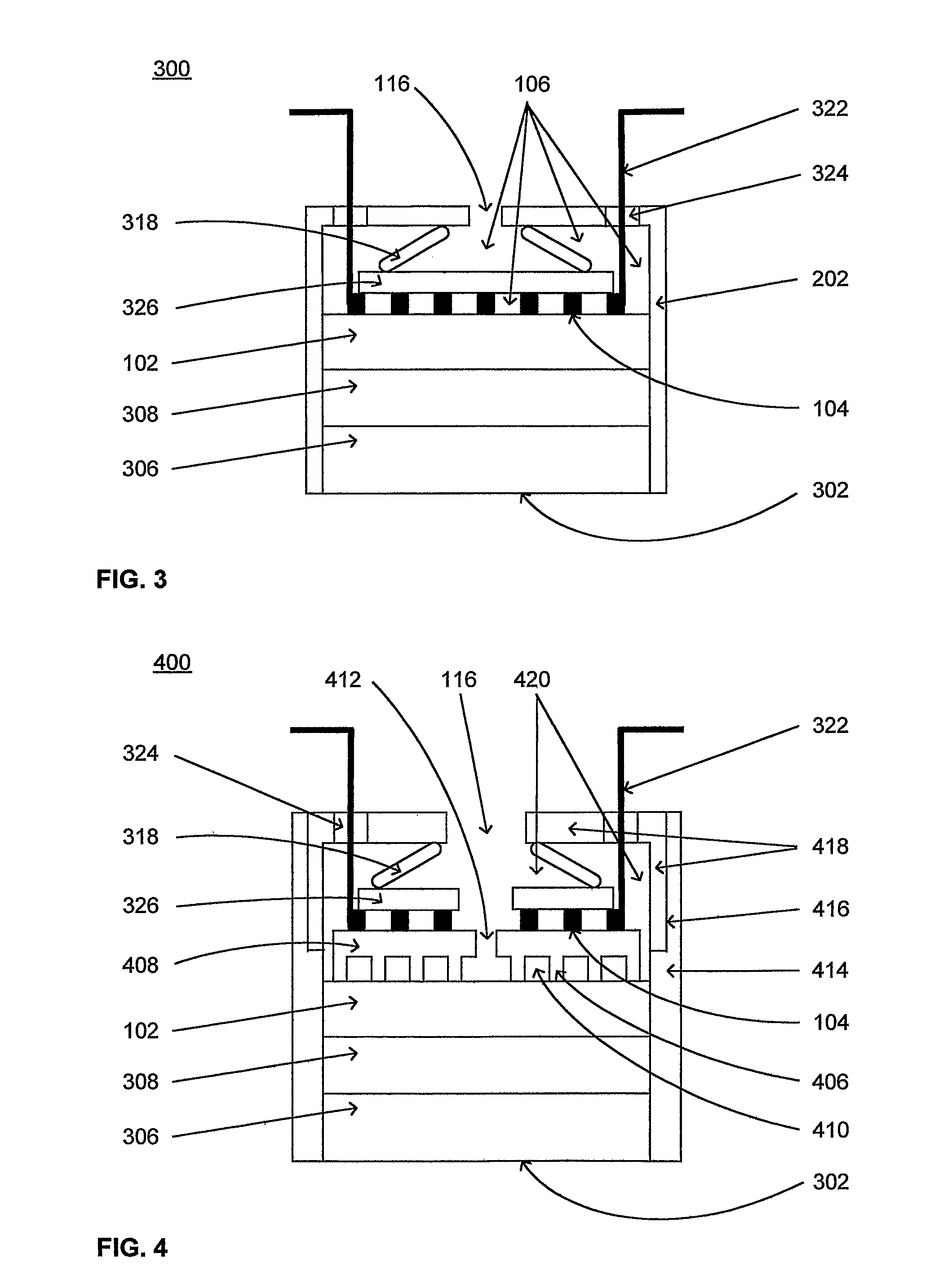
[0074]A capillary force vaporizer module was manufactured according to the embodiments of the present invention as shown in FIG. 4. The diameter of porous member 102 was 19 mm and its thickness was 1 mm. The external diameter of the device was about 30 mm. The porous member and insulator component were fabricated from highly porous alumina using known techniques. See, for example, U.S. Pat. No. 6,585,509 and U.S. Pat. No. 6,634,864. The vaporizer material had a mean pore size of about 1 micron (μm) and the total porosity was about 80%. The insulator component had a mean pore size of about 20 μm and the total porosity was about 80%. The heat exchanger component was manufactured from approximately 96% dense aluminum oxide, and the material, design and manufacturing methods were similar to those used to manufacture the orifice component in prior art CFV devices.

[0075]The external housing in Example 1, which comprised upper and lower housing sections, was made from Teflon plastic by sta...

examples 2a and 2b

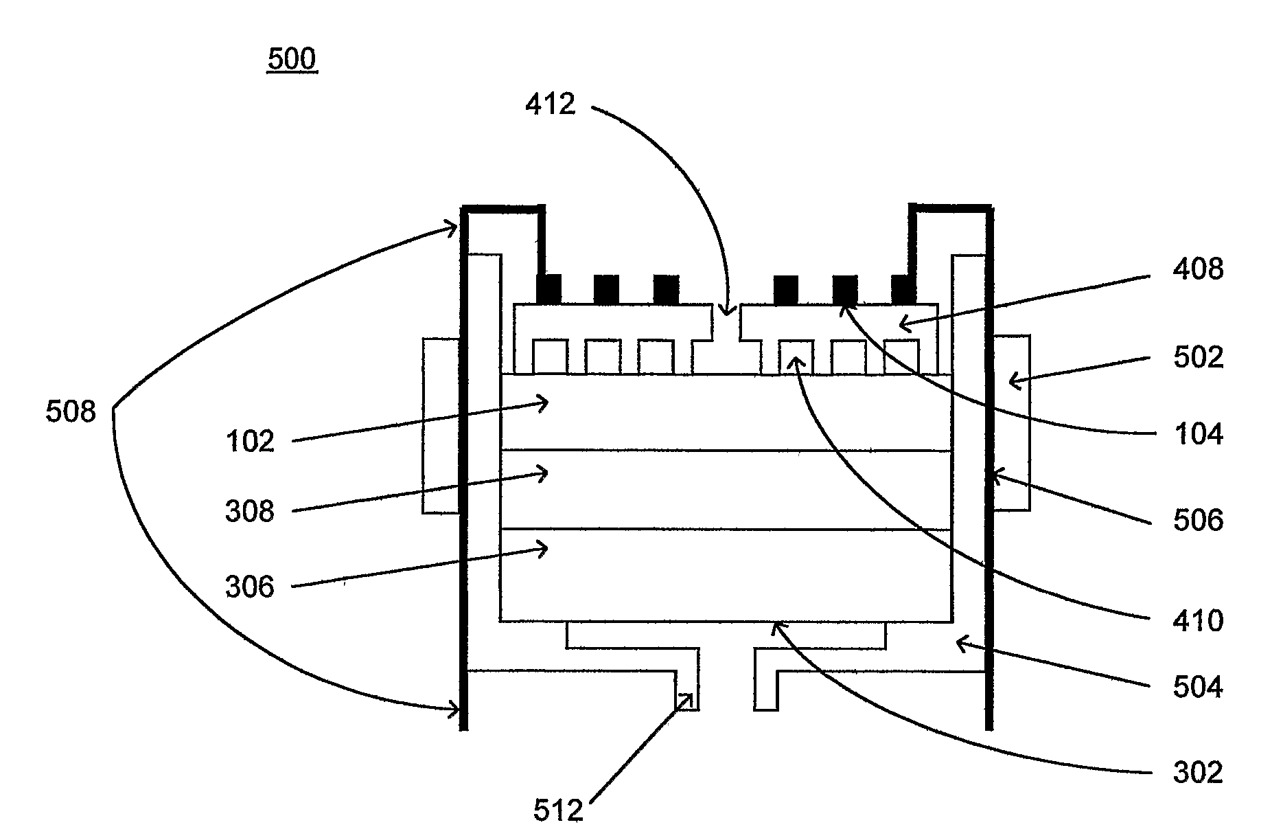
[0079]A capillary force vaporizer module was manufactured according to the embodiment of the present invention shown in FIG. 5A. Both the outer and inner housing components, corresponding to 502 and 504, respectively, of FIG. 5A, in Example 2a were machined from aluminum metal, and a simple set screw was used to hold the components together. The capillary force vaporizer module of this example was connected to a 200 watt power supply that was controlled by a software program via computer interface, thus forming an integrated capillary force vaporizer system as shown in FIG. 8. Using distilled water as a test liquid, the device was operated successfully over a wide range of power settings similar to Example 1 above and the performance characteristics were recorded. Within the margins of measurement errors, the device performance characteristics were found to be essentially identical to those of the present invention device of Example 1, as shown in Table 1, with the exception that th...

example 3

[0081]Next, a complete vaporization system as shown in FIG. 7 was assembled as follows. The liquid supply component was removed from the capillary force vaporizer of Example 2b. A custom fitted liquid supply component made from the same material was machined so that one end of the liquid supply component fit directly into the end of a polyethylene liquid supply hose that was connected to a flexible gravity feed reservoir. The other end of the liquid supply component was machined to fit directly into the bottom of the capillary force vaporizer such that when fully assembled, the capillary force vaporizer was connected directly to the liquid supply hose using the liquid supply component to hold the system together.

[0082]The system and device of Example 3 was operated successfully over the same range of conditions as in Example 1, and, within the measurement errors, the performance characteristics were essentially similar to those shown previously in Table 1 for Example 1 as well as Ex...


PUM

PropertyMeasurementUnit
Weightaaaaaaaaaa
Porosityaaaaaaaaaa
Porosityaaaaaaaaaa

Abstract

The present invention concerns capillary force vaporizers for use in vaporizing liquids and emitting pressurized vapors. In one embodiment, the inventive capillary force vaporizer includes a porous member, a heater component to convey heat to the porous member, and a vapor containment region. The porous member further includes a capillary network, a surface for receiving liquid and a vaporization area in which vapor is produced from the liquid. The vapor is collected and pressurized within the vapor containment region, which includes one or more openings for the release of vapor at a velocity greater than zero. Several different embodiments for capillary force vaporizers and systems comprising capillary force vaporizers are disclosed along with methods for their use.

Description

[0001]The present invention is a continuation-in-part of commonly-assigned and co-pending application for patent U.S. Ser. No. 10 / 691,067 filed 21 Oct. 2003.BACKGROUND OF THE INVENTION[0002]1. Field of the Invention[0003]The present invention relates to the vaporization of liquids and the pressurization of vapors in capillary force vaporizers. More particularly, the invention relates to improved capillary force vaporizers, as well as capillary force vaporizer modules and systems for producing vapor for a variety of applications.[0004]2. Description of the Pertinent Art[0005]Many applications utilize gases that have been generated from liquid sources. Vaporization devices have been designed to vaporize liquids and release the resulting vapor under pressure. In applications in which a pressurized vapor stream is desired, prior art devices generally require that liquid be supplied to the device under pressure, or that the vapor is otherwise pressurized by external means. For example, i...

Claims


Application Information

Patent Timeline
IPC IPC(8): F22B1/28B23P19/04F22B27/06
CPCA01M1/2077A61L9/037A61M16/1075A61M16/16A61M2205/3368F04B19/24A61M16/109A61M16/142A61M16/147A61M16/0833Y10T29/49826A61M2205/3653A61M16/021
Inventor RABIN, BARRY H.SELLERS, CHARLES H.BRESLAU, WARREN S.DAVIDSON, ERICK M.
Owner VAPORE
Why Eureka
Try Eureka