Prosthetic socket with real-time dynamic control of pressure points

a pressure point and prosthesis technology, applied in prosthesis, medical science, artificial legs, etc., can solve the problems of high pressure the volume of the residual limb changes significantly, and the persistence of localized pressure points in the contact between the residual limb and the socket, so as to facilitate multiple pressure control points and reduce high pressure points

Inactive Publication Date: 2008-06-19
WISYS TECH FOUND
View PDF7 Cites 51 Cited by
  • Summary
  • Abstract
  • Description
  • Claims
  • Application Information

AI Technical Summary

Benefits of technology

[0007]The present invention provides a cushioned socket for a prosthetic leg using a dynamically controlled system of pressure sensors and valves that selectively control the local pressure in a fluid filled and fluid permeable liner. The liner provides viscoelastic properties that moderate the pressure equalization process to reduce high pressure points while still providing a secure fit between the residual limb and the socket and facilitating multiple points of pressure control.
[0013]It is thus another object of one embodiment of the invention to provide for multiple dimensions of fluid flow permitting greater flexibility in the tailoring of the property at a given zone.
[0015]It is thus another object of one embodiment of the invention to provide a material that can have a controlled porosity allowing a variety of different materials to be readily implemented.
[0019]It is thus another object of one embodiment of the invention to allow flexible tailoring of the elasticity of the liner independently from its viscous flow properties.

Problems solved by technology

Unfortunately the volume of the residual limb changes significantly over time and even within the course of a day making a good fit between the residual limb and socket difficult to maintain.
A difficult problem for patients, even with padded sockets that properly conform to the surface of the residual limb, is the persistence of localized points of high pressure in the contact between the residual limb.
Such persistent high pressure points can result from difficult to correct socket interface pressure that occurs during human activities such as running, jumping, leaning and lifting which cause large variations in the loading on the residual limb, and the need to maintain a relatively stiff interface between the residual limb and the socket to prevent undue “bouncing” movement of the prosthetic leg during use.
Such persistent high pressure points may cause discomfort to the patient which can deter the use of the prosthetic leg and, in extreme cases, can cause tissue damage.

Method used


Image

  • Prosthetic socket with real-time dynamic control of pressure points
  • Prosthetic socket with real-time dynamic control of pressure points
  • Prosthetic socket with real-time dynamic control of pressure points

Examples


Embodiment Construction

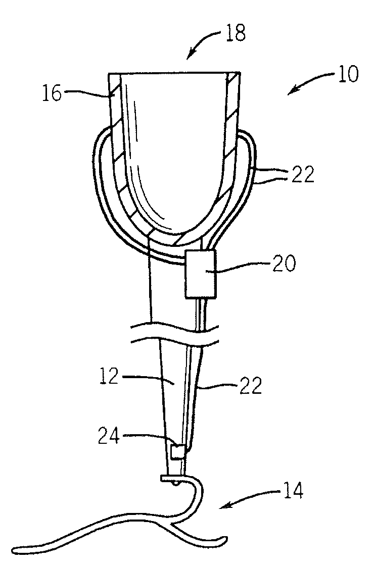
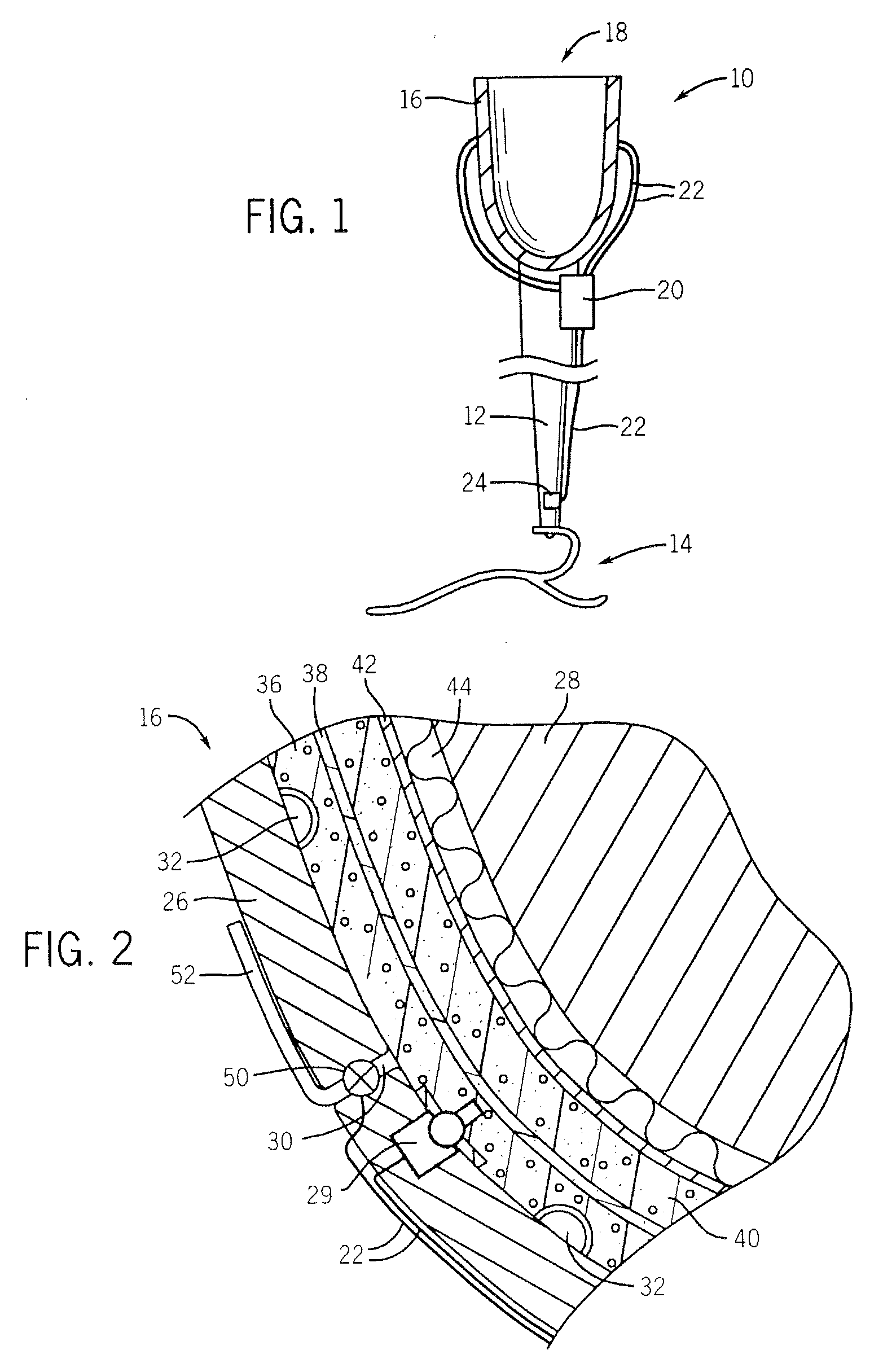
[0029]Referring now to FIG. 1, a prosthetic leg 10 may include a leg shaft 12 terminating at its lower end with a foot portion 14 and at its upper end by a socket 16. The socket 16 defines a volume 18 opening upwardly to receive the residual limb 28 of a patient (not shown in FIG. 1). A battery powered micro computer 20 may be attached to the prosthetic leg 10 to receive signals over signal lines 22 from valves and sensors in the socket 16 (to be described below) and a stride sensor 24, such as a spring-loaded switch, accelerometer, or strain gauge, sensing force or acceleration on the leg shaft 12 indicating a stride portion of the patient's gait.

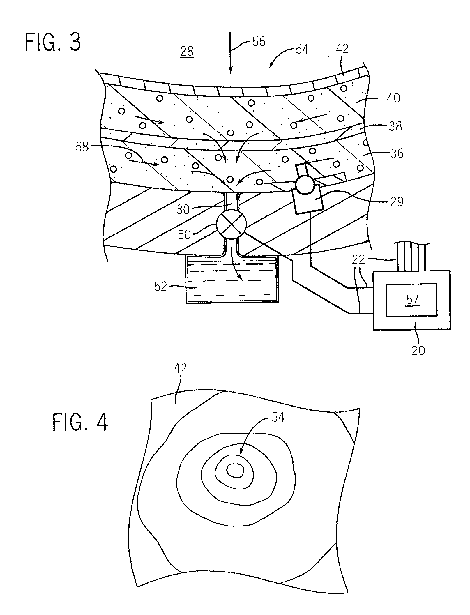
[0030]Referring now also to FIG. 2, the socket 16 may include an outer rigid shell 26 conforming generally to the outer surface the residual limb 28. The shell 26 may be attached directly to the shaft 12 to communicate forces there between.

[0031]At various locations on the inner surface of the shell 26, pressure sensors 29 are placed, near...


PUM


Abstract

An improved socket for a prosthesis uses a liner material providing fluid flow through a porous matrix whose local pressure is adjusted by a control system communicating with multiple valves and pressure sensors. Control of pressure in a viscoelastic material provides an improved trade-off between comfort and stability.

Description

CROSS REFERENCE TO RELATED APPLICATION[0001]This application claims the benefit of U.S. provisional application 06 / 870,492 filed Dec. 18, 2006 hereby incorporated by reference.BACKGROUND OF THE INVENTION[0002]The present invention relates to prosthetic devices, and in particular to a prosthetic device that may sense points of high pressure contact with a patient's residual limb and locally reduce those pressures on a dynamic basis.[0003]Lower limb amputees may be fitted with a prosthetic leg that attaches to their residual limb by means of a socket surrounding the residual limb. In such cases, it is important that the socket fit closely to the residual limb so that the amputee has a sense that the prosthetic limb is secure and stable and the forces of walking are distributed evenly over the entire residual limb. It is also important that the fit not be so tight as to restrict blood flow or to be uncomfortable.[0004]Unfortunately the volume of the residual limb changes significantly ...

Claims


Application Information

Patent Timeline
Patent Type & Authority Applications(United States)
IPC IPC(8): A61F2/60A61F2/72
CPCA61F2/60A61F2/68A61F2/7812A61F2/7843A61F2/80A61F2002/7655A61F2002/704A61F2002/745A61F2002/748A61F2002/7635A61F2002/764A61F2002/5012A61F2/70A61F2/74A61F2/748
Inventor EZENWA, BERTRAM
Owner WISYS TECH FOUND
Why Eureka
Try Eureka