Motor vehicle lock

a technology for motor vehicles and latches, applied in electrical locking circuits, building locks, constructions, etc., can solve problems such as the risk of the pawl re-engaging with the catch, and achieve the effects of simple construction, increased functional safety of the motor vehicle latch, and cost-effectiveness

Active Publication Date: 2021-08-24
KIEKERT AG
View PDF20 Cites 0 Cited by
  • Summary
  • Abstract
  • Description
  • Claims
  • Application Information

AI Technical Summary

Benefits of technology

[0009]The task of the invention is to provide an improved motor vehicle latch. In particular, it is a task of the invention to increase the functional safety of motor vehicle latches and to guarantee engagement of the locking mechanism functions at any time with the greatest level of safety. Furthermore, it is a task of the invention to provide a cost-effective motor vehicle latch of a simple construction.

Problems solved by technology

In this case, the catch engaged with the latch holder cannot completely leave the engagement area of the pawl or pivot out of the engagement area of the pawl so that there is a risk of the pawl re-engaging with the catch.
A problem which can arise on motor vehicle latches with a storage function is that when the locking mechanism is locked the pawl and / or the triggering lever can be conducted by means of the catch and, according to the activation speed of the catch, can experience an impulse during closure by the catch.

Method used


Image

  • Motor vehicle lock
  • Motor vehicle lock
  • Motor vehicle lock

Examples


Embodiment Construction

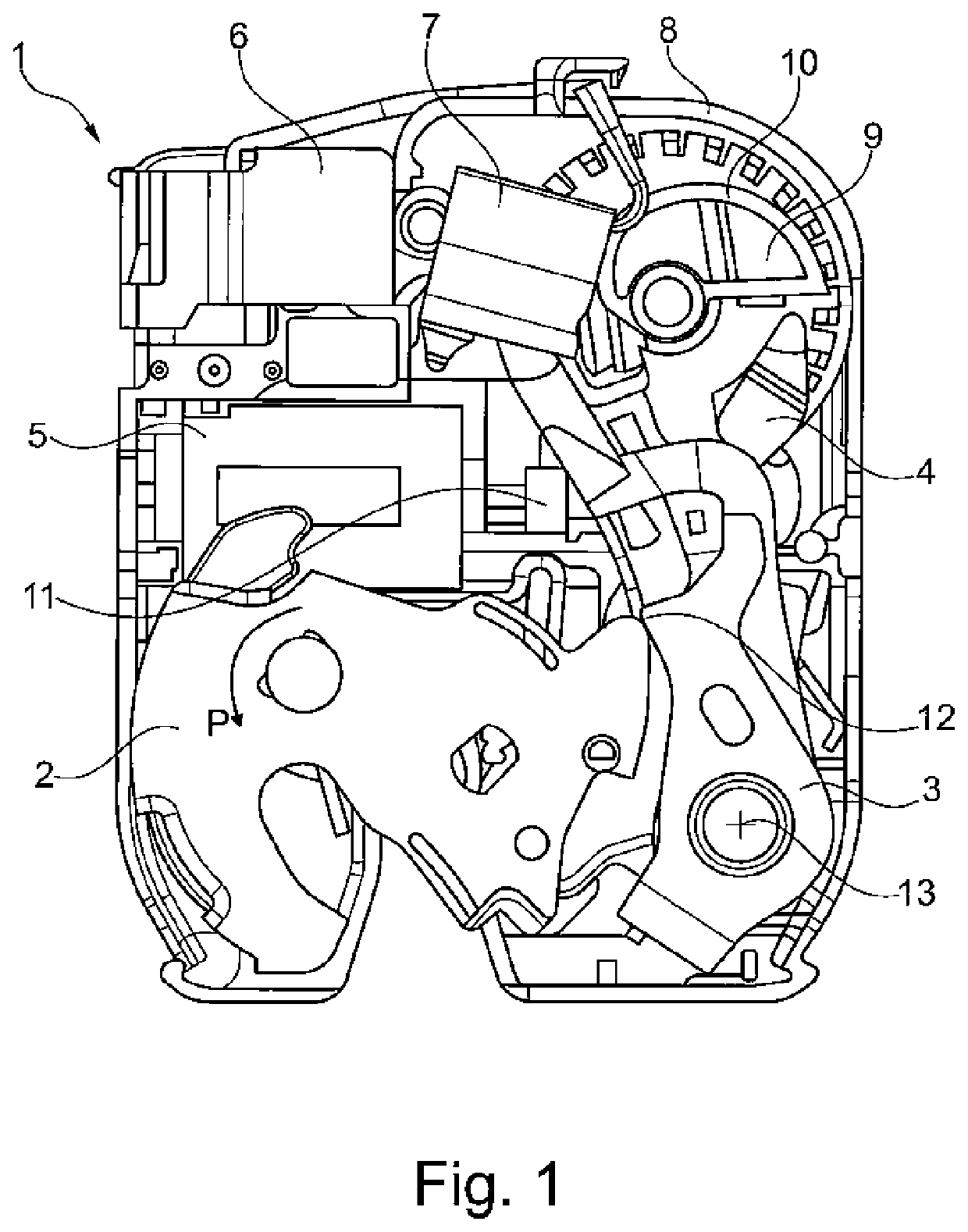
[0034]FIG. 1 reproduces a motor vehicle latch 1 and in particular a tailgate latch 1, in a top view and without a latch lid. The motor vehicle latch 1 has a catch 2, a pawl 3, a triggering lever 4 and an electrical drive 5. The following are furthermore apparent.

[0035]Switching means 6, 7, a latch housing 8 and a gearwheel 9 with a control contour 10. A wormgear 11 is arranged between the electrical drive 5, which is preferably an electromotor and the gearwheel 9, so that the gearwheel 9 can be electrically activated.

[0036]The open position of the catch 2 is reproduced in FIG. 1. By means of closure of a door or flap, the motor vehicle latch 1 is moved against a non-illustrated latch holder so that the catch accomplishes a movement in the direction of the arrow P in a counterclockwise direction. In the opening position, the pawl 3 is adjacent on the adjacency contour 12 of the catch. The pawl 3 preferably lies adjacent in a spring pre-tensioned manner against the catch 2, whereby th...


PUM


Abstract

The invention relates to a motor vehicle lock (1) comprising a locking mechanism that includes a rotary latch (2), at least one pawl (3), a triggering lever (4) that allows the pawl (3) to disengage from the rotary latch (2), and a latching lever function that allows the triggering lever (4) which is actuated for disengaging the rotary latch (2) to be secured in an actuated position; the triggering lever can be guided by the rotary latch (2) only in some sections.

Description

FIELD OF THE INVENTION[0001]The invention relates to a motor vehicle latch having a locking mechanism with a catch and at least one pawl, a triggering lever, whereby by means of the triggering lever the pawl can be disengaged from the catch, a storage lever function, whereby by means of the storage lever function a triggering lever activated to disengage the catch can be fixed in an activated position.BACKGROUND OF THE INVENTION[0002]In order to increase functional safety in motor vehicles, the motor vehicle latches used in the flaps, doors, sliding doors or hoods are equipped with a multitude of functions. One of these functions is that relatching or incomplete opening is prevented also in the case of opening of a locking mechanism in a motor vehicle latch.[0003]In particular where the latch is a tailgate latch, it is possible that after electrical or manual opening of the latch the locking mechanism remains in the engagement area of the latch holder as the flap is acted upon with ...

Claims


Application Information

Patent Timeline
Patent Type & Authority Patents(United States)
IPC IPC(8): E05B85/26E05B81/14E05B81/68E05B85/24E05B81/66
CPCE05B85/26E05B81/15E05B81/66E05B81/68E05B85/243
Inventor SCHIFFER, HOLGER
Owner KIEKERT AG
Why Eureka
Try Eureka