
Continuously variable transmission with uniform input-to-output ratio that is non-dependent on friction

a transmission ratio, continuous variable technology, applied in the direction of friction gearings, belts/chains/gears, friction gearings, etc., can solve the problems of inability to use, and achieve the effect of uniform and steady output, lack of transmission ability, and high torqu

Active Publication Date: 2021-08-24
RAJENDRAN RAJA RAMANUJAM +1
View PDF8 Cites 0 Cited by
  • Summary
  • Abstract
  • Description
  • Claims
  • Application Information

AI Technical Summary

Benefits of technology

[0007]The main objective of this invention is to provide a UNIFORM and STEADY output, when the input is uniform and steady, with the ability to transmit high torque without depending on friction or friction factor. Many of the continuously variable transmissions that are in the market today are friction dependent and therefor lack the ability to transmit high torque. Those continuously variable transmissions, which are non-friction dependent do not have a uniform and steady output when the input is uniform and steady. This design aids reduction in the overall size and can be economically mass produced. This design can be easily integrated into any system. This design is very versatile and can be used ranging from light duty to heavy duty applications. This design allows replacement of existing regular transmission, requiring very little modification. This design offers stationary and co-axial input and output.

Problems solved by technology

Most of the CVTs that exist today depend on friction to transmit power and therefore cannot be used where there is a need to transmit high power at low speed.

Method used


Image

  • Continuously variable transmission with uniform input-to-output ratio that is non-dependent on friction
  • Continuously variable transmission with uniform input-to-output ratio that is non-dependent on friction
  • Continuously variable transmission with uniform input-to-output ratio that is non-dependent on friction

Examples


Embodiment Construction

Summary of the Invention

[0215]To briefly describe this invention is a Continuously Variable Transmission (CVT). Unlike existing CVT designs, this particular design does NOT depend on friction to transmit power. Most of the CVTs that exist today depend on friction to transmit power and therefore cannot be used where there is a need to transmit high power at low speed. Due to this advantage, it is possible to use this invention where high torque transmission is required. Co-axial input and output can be achieved with this layout.

LIST OF COMPONENTS

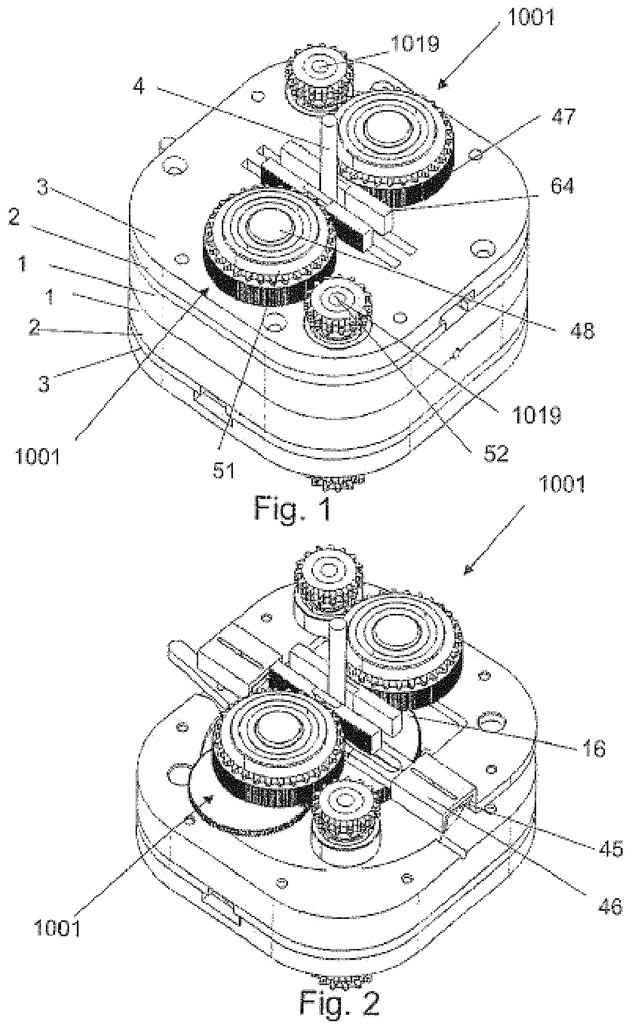
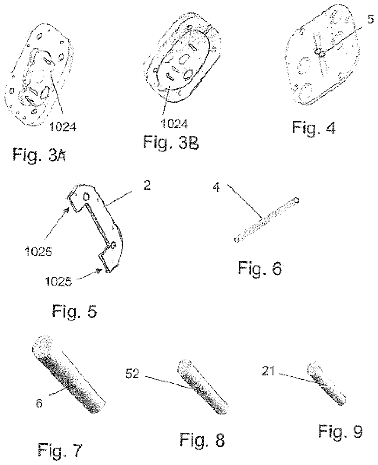
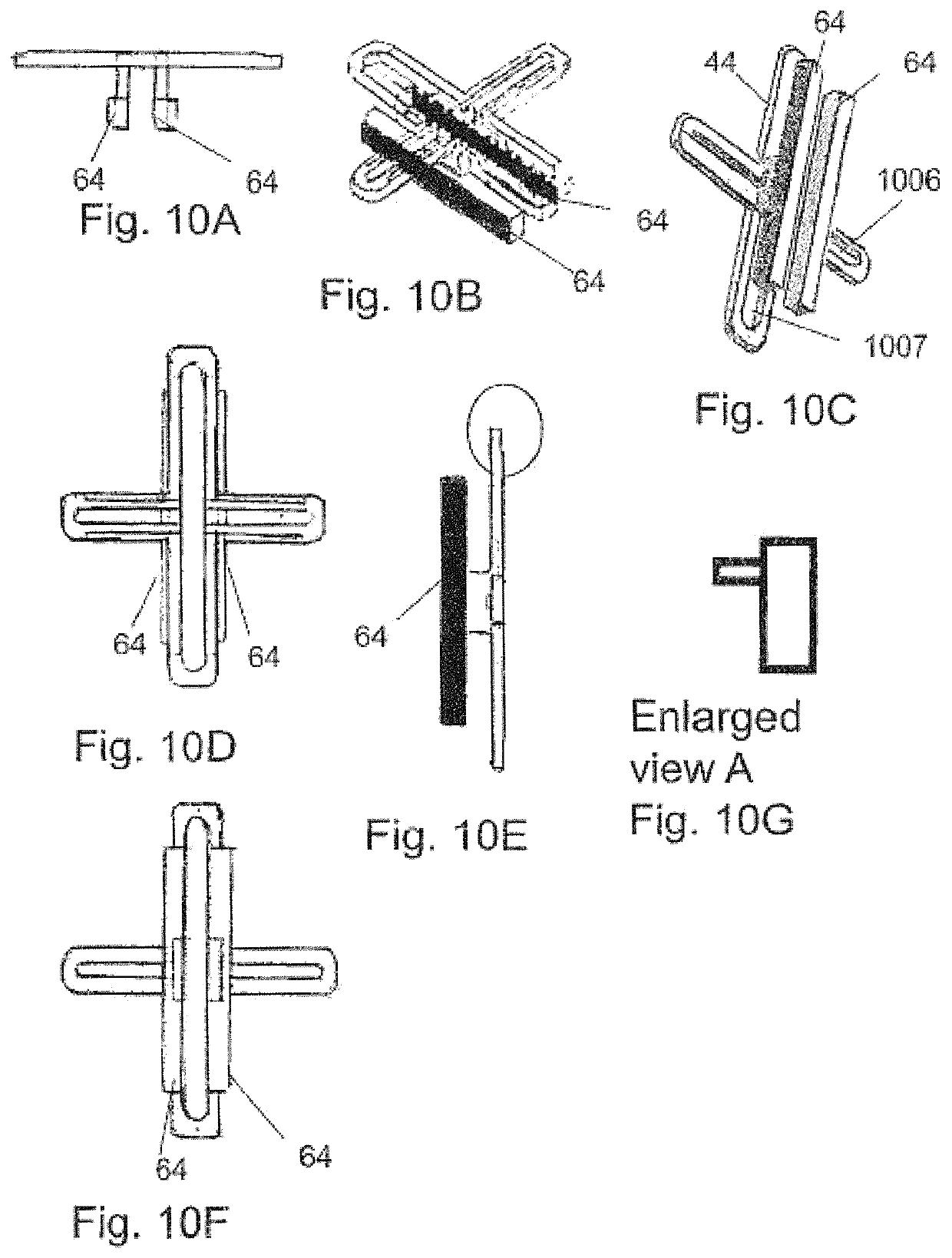
[0216]1) Main housing frame[0217]2) Cross rack holder frame[0218]3) Telescopic guide frame[0219]4) Input shaft[0220]5) Input shaft bearing[0221]6) Intermediate gear shaft[0222]7) Intermediate gear shaft bearing[0223]8) Driving non-circular gear[0224]9) Driven non-circular gear[0225]10) Intermediate circular gear c1[0226]11) Intermediate circular gears c2 c3[0227]12) Intermediate circular gears c4 c5[0228]13) Bearing collar[0229]14) Circular g...


PUM


Abstract

This invention is an all gear continuously variable transmission that is non-dependent on friction. It can me be used in high torque applications. It offers a steady and uniform output for a steady and uniform input. It allows a co-axial input and output thereby by using a planetary gear system the output can be made continuous from forward to reverse. This uses a “scotch-yoke” mechanism to convert rotational motion to a linear reciprocating motion. The linear distance of this reciprocating motion-“stroke” is changed by altering the crankpin location of the scotch-yoke mechanism. This reciprocating motion is converted to a rocking motion by using a “rack and pinion” and later converted to a unidirectional motion via a One-Way-Bearing. A set of non-circular gears are used to achieve a steady and uniform output. It employs a very simple mechanism to change the ratio between the input and output of the transmission.

Description

CROSS REFERENCE TO RELATED APPLICATIONS[0001]Provisional Application[0002]Application Number: 61788563BACKGROUND OF THE INVENTIONField of the Invention[0003]This invention pertains to transmissions having variable ratios between input and output velocities. Specifically, it relates to all-gear transmissions whose velocity ratios may be changed continuously over a wide range of values, without depending on friction.Description of the Related Art[0004]The U.S. Pat. No. 5,603,240 and US 20100199805 use some of the features used in this design. The advantages in this invention include:[0005]The U.S. Pat. No. 5,603,240 does not have a co-axial input to output and therefore cannot be used for applications requiring this configuration. The output travels as the ratio is changed. Therefore, this design cannot be used when stationary output is required. This new invention offers a stationary and co-axial input and output shaft. The envelope used in this invention is comparably smaller than t...

Claims


Application Information

Patent Timeline
Patent Type & Authority Patents(United States)
IPC IPC(8): F16H29/20F16H21/36F16H29/08F16H29/00F16H19/04F16H35/00F16H29/14F16H29/18F16H35/02
CPCF16H29/20F16H21/36F16H29/00F16H29/08F16H19/043F16H29/14F16H29/18F16H35/02F16H2035/003
Inventor RAJENDRAN, RAJA RAMANUJAMRAJENDRAN, PRASHANTH RAM
Owner RAJENDRAN RAJA RAMANUJAM
Learn More