
Connector mounting mechanism

a technology of connecting wire and mounting mechanism, which is applied in the direction of coupling device connection, coupling device engagement/disengagement, testing/measuring connectors, etc., can solve the problems of connecting wire not being standardized, the connection at the two ends may not be easily pulled out, and the test result may also deviate from the actual situation

Active Publication Date: 2021-08-24
MINGSHUO COMP (SUZHOU) CO LTD +1
View PDF5 Cites 0 Cited by
  • Summary
  • Abstract
  • Description
  • Claims
  • Application Information

AI Technical Summary

Benefits of technology

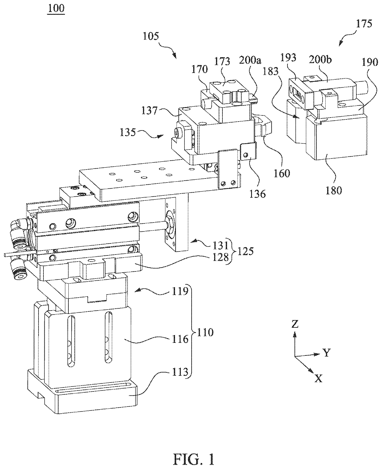
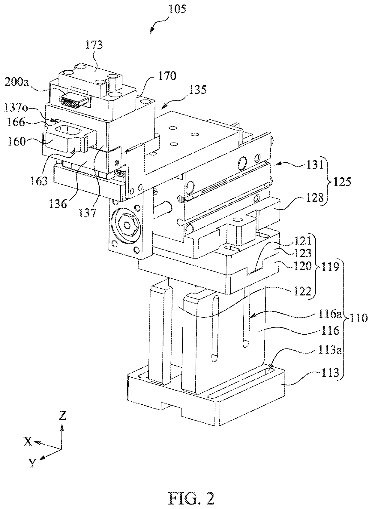
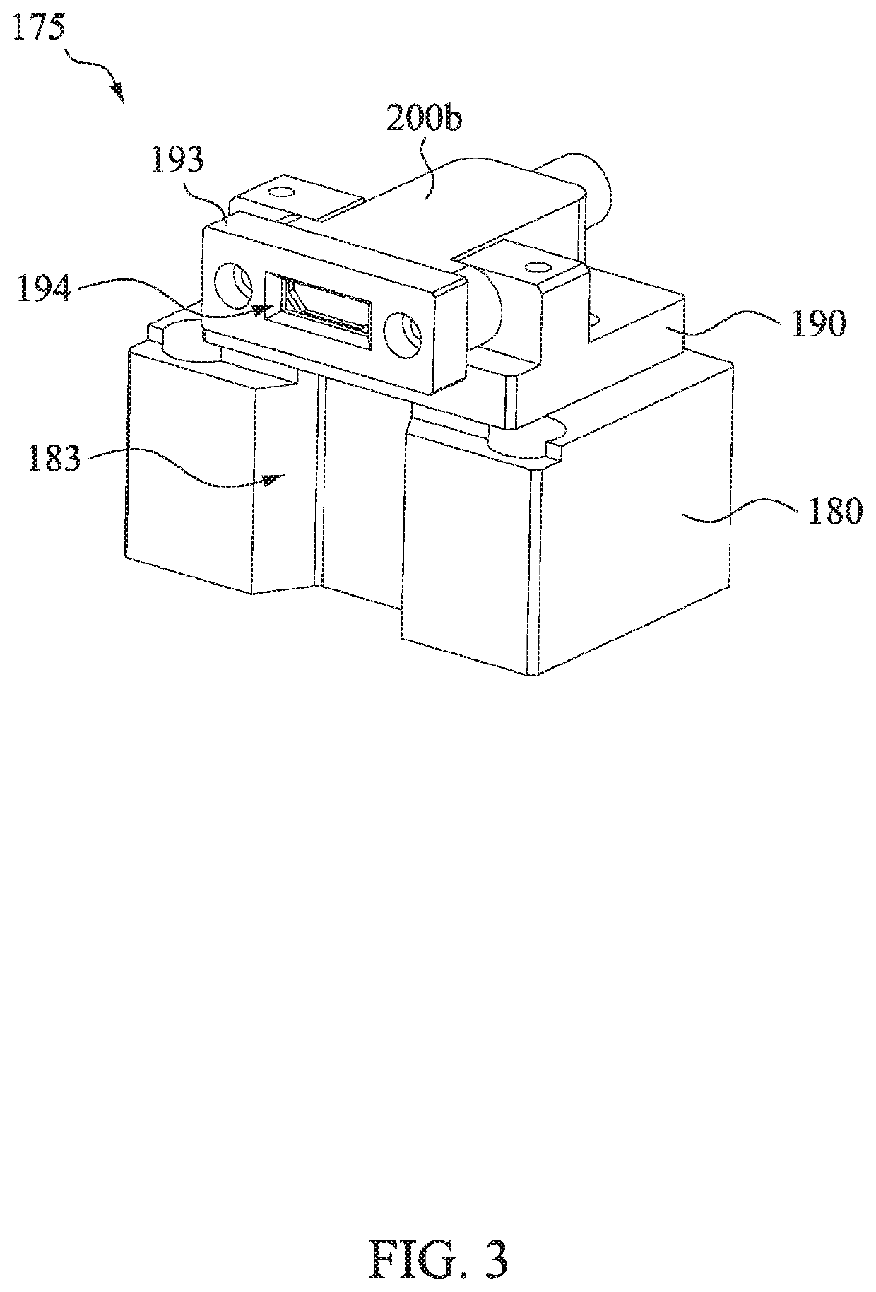
[0019]According to one or more implementations of the present disclosure, the connector mounting mechanism in the present disclosure is configured to plug the first connector into the second connector. After a position of the second connector is fixed, the first connector is roughly positioned at the second connector via the base. A position of the first connector is adjusted finely and guided via a coupling between the first position guide block and the second position guide block. Due to the guide buffer module, the coupling positioning of the first position guide block and the second position guide block may be automatic and flexible. The first connector can be plugged into the second connector via the guide of the first joint guide block and the second joint guide block. Accordingly, in the present disclosure, the first connector can be plugged into the second connector normally and smoothly without additional processing on the first connector. In this case, results of corresponding tests on the first connector and the second connector may be more accurate and reasonable. In some actual implementations, the first connector and the second connector may be two joints respectively corresponding to an HDMI. However, the present disclosure is not limited thereto.

Problems solved by technology

Generally, to avoid the wire falling off unexpectedly during information transmission, the joints at the two ends of the connecting wire may be designed to be clamped very tightly, so that the joints at the two ends may not be easily pulled out.
However, this may make the test of the connecting wire not standardized, and the test result may also deviate from the actual situation.

Method used


Image

  • Connector mounting mechanism
  • Connector mounting mechanism
  • Connector mounting mechanism

Examples


Embodiment Construction

[0031]Embodiments are given below in detail with reference to the accompanying drawings, but the embodiments provided are not intended to limit the scope of the present disclosure, and the description of a structure operation is not used for limiting the sequence of steps. Any device with equal efficiency produced by a structure recombined by elements is within the scope of the present disclosure. In addition, the accompanying drawings are merely for describing and are not drawn in accordance with the original size. For ease of understanding, the same or similar elements in the description below may be indicated by the same labels.

[0032]In addition, for terms used in the entire specification and claims, unless stated particularly, the common meaning of each word used in the field and in the content of the present disclosure and in the particular content is provided. Certain terms used for describing the present disclosure may be discussed below or elsewhere in this specification to ...


PUM


Abstract

A connector mounting mechanism includes a base, a power module, a guide buffer module, a first position guide block, a first joint guide block, a second position guide block, and a second joint guide block. The first position guide block is connected with the power module and movably received in the guide buffer module. The first joint guide block is disposed on the guide buffer module and connected with the power module, and is configured to fix a first connector. The second joint guide block is disposed at the second position guide block and configured to fix a second connector. The power module drives the first joint guide block to be plugged into the second joint guide block after driving the first position guide block to be guided into the second position guide block.

Description

CROSS-REFERENCE TO RELATED APPLICATION[0001]This Non-provisional application claims priority under 35 U.S.C. § 119(a) on Patent Application No(s). 201910646069.4 filed in People's Republic of China on Jul. 17, 2019, the entire contents of which are hereby incorporated by reference.BACKGROUNDField of Invention[0002]The present disclosure relates to a connector mounting mechanism, and in particular, to a connector mounting mechanism that can plug the first connector into the second connector precisely.Description of Related Art[0003]If 3C products in the market need to be connected with other devices, additional connecting wires need to be used. For example, if a notebook computer needs to output an image to an external screen, a high definition multimedia interface (HDMI) adapter needs to be used. Accordingly, transmission quality of the connecting wires is important for the 3C products, and many related manufacturers may have corresponding test machines.[0004]The test on a connectin...

Claims


Application Information

Patent Timeline
Patent Type & Authority Patents(United States)
IPC IPC(8): H01R13/631
CPCH01R13/631H01R43/26H01R2201/06H01R2201/20
Inventor LIN, TIEN-JU
Owner MINGSHUO COMP (SUZHOU) CO LTD
Learn More