

Video encoding system and video encoding method
Patent Information
- Authority / Receiving Office
- US · United States
- Patent Type
- Patents(United States)
- Current Assignee / Owner
- PANASONIC I PRO SENSING SOLUTIONS CO LTD
- Publication Date
- 2021-08-24
Smart Images
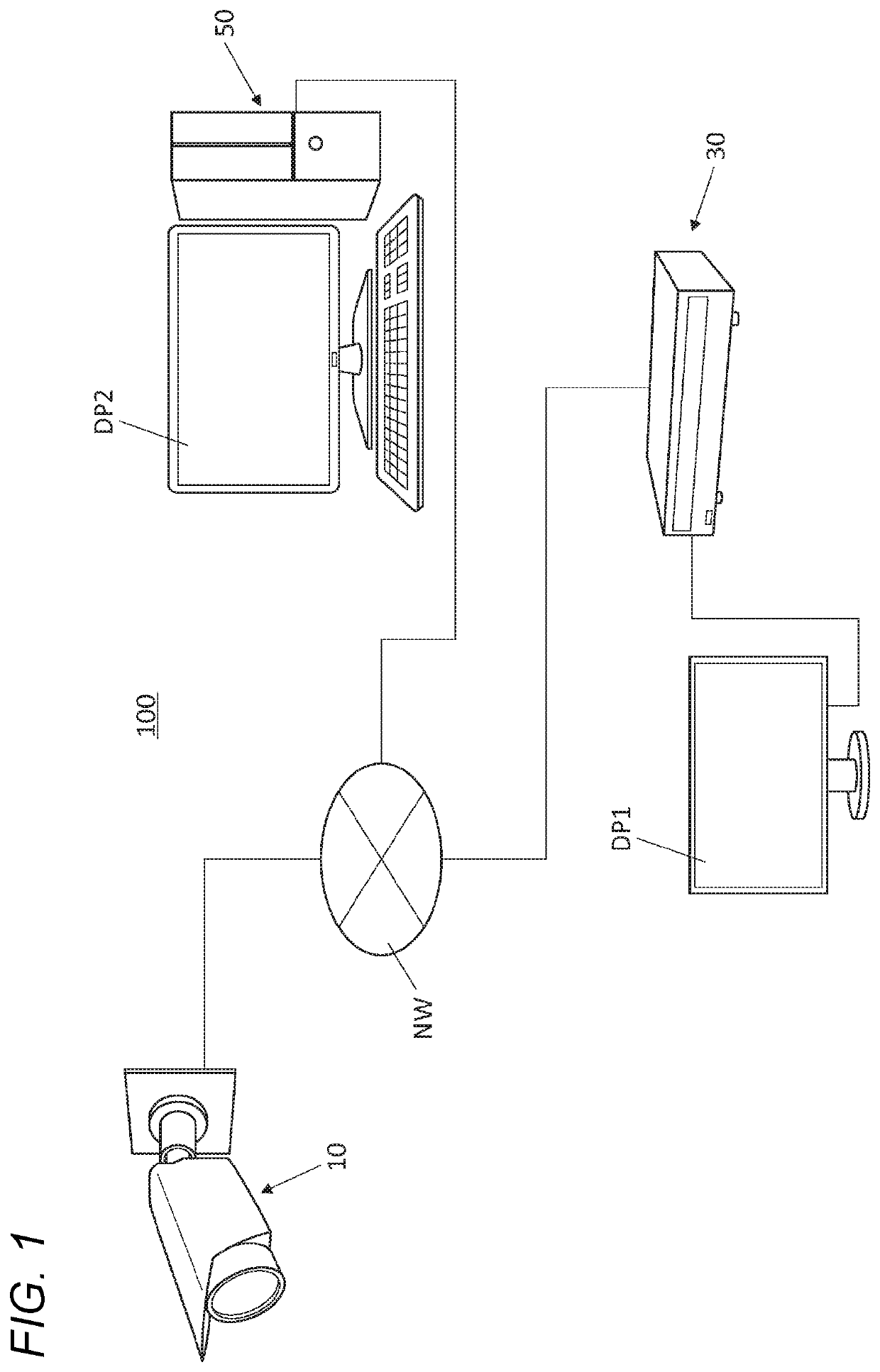
Figure 1 
Figure 2 
Figure 3
Abstract
Description
BACKGROUND OF THE INVENTION1. Field of the Invention
[0001] The present disclosure relates to a video encoding system and a video encoding method for encoding a video captured by a camera.2. Background Art
[0002] In JP-A-2014-22970, in an image recognition and authentication system that transmits an image obtained by photographing with a camera to an image reception apparatus and performs a recognition authentication process of a subject based on an image by the image reception apparatus, an image transmission apparatus that suppresses a decrease in recognition accuracy is disclosed. The image transmission apparatus reduces the data amount of a plurality of input images, by a reduction method according to the recognition authentication process performed by the image reception apparatus. For example, the image transmission apparatus reduces the data amount of a plurality of images by selecting a part of images from among a plurality of images, based on the recognition authentication proc...