Method for monitoring rolling bearings

a technology for rolling bearings and monitoring devices, applied in mechanical equipment, mechanical energy handling, instruments, etc., can solve the problems of low reliability, low reliability, wear and timing of bearing breakdown, etc., and achieve the effect of reducing downtime as well as maintenance costs, improving the availability of ec motors, and high residual li

Active Publication Date: 2021-08-31
EBM PAPST MULFINGEN GMBH & CO KG
View PDF11 Cites 0 Cited by
  • Summary
  • Abstract
  • Description
  • Claims
  • Application Information

AI Technical Summary

Benefits of technology

[0010]It is therefore the object of the disclosure to overcome previously mentioned drawbacks and provide a reliable and inexpensively achievable solution for monitoring the bearing state and specifically for detecting damage to the rolling bearing.
[0021]To reduce interferences caused by other sources of interference, such as, for example, radio emitters, sources of interference in the motor etc., while measuring, a preferred embodiment of the disclosure proposes that the receiver only detects a particular frequency band of electromagnetic waves. It is especially advantageous if this frequency band is selectively tuned to the resonant frequency of the EC motor parasitic sending antenna.

Problems solved by technology

However, the downside is that it is rarely possible to accurately predict the state, wear and timing of bearing breakdown.
Furthermore, early replacement of parts having a high residual life is a common occurrence in preventive maintenance.

Method used


Image

  • Method for monitoring rolling bearings
  • Method for monitoring rolling bearings
  • Method for monitoring rolling bearings

Examples


Embodiment Construction

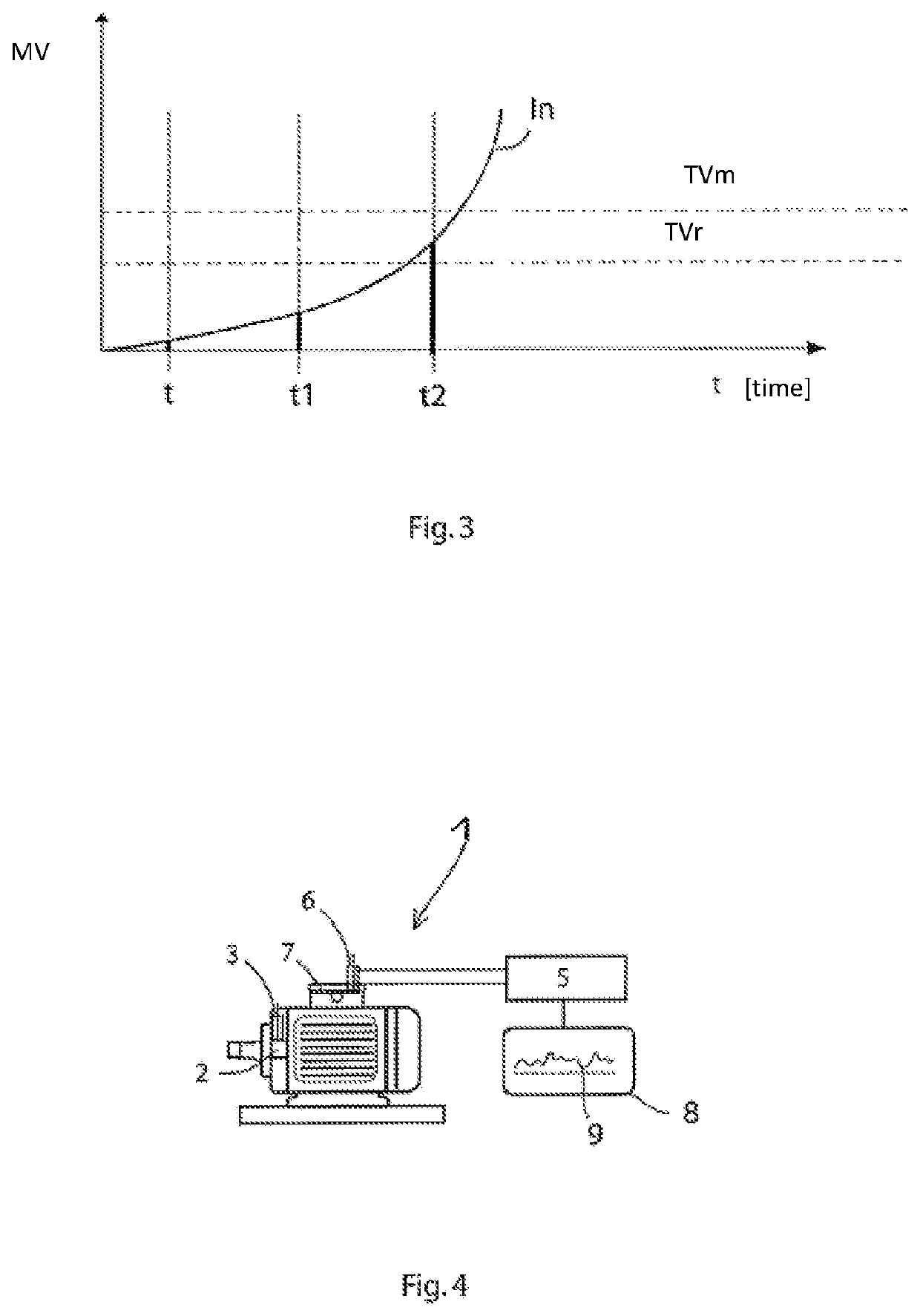
[0032]The disclosure will subsequently be described in further detail based on preferred exemplary embodiments with reference to the FIGS. 1 to 4, wherein same reference numerals indicate same functional and / or structural characteristics.

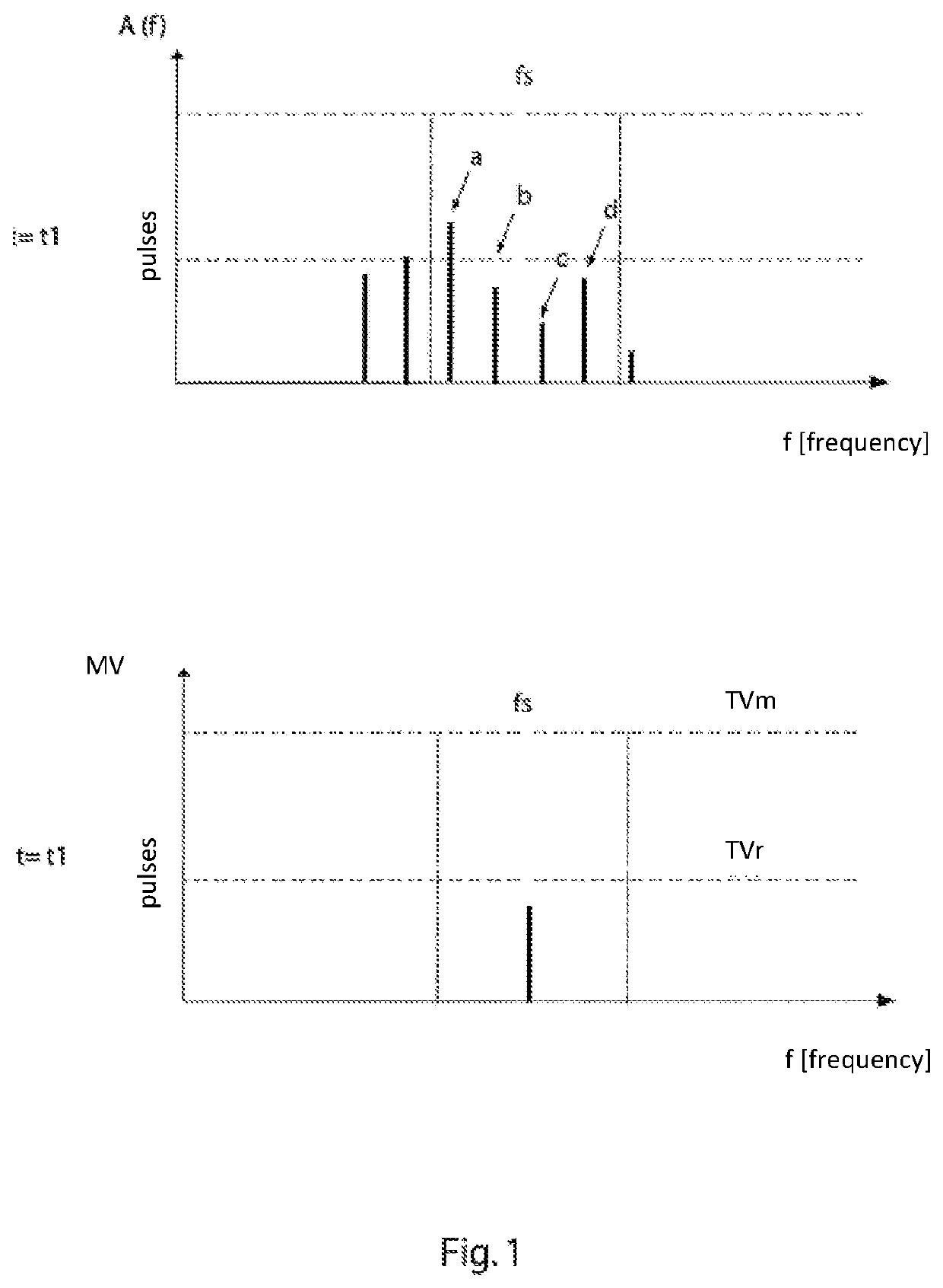
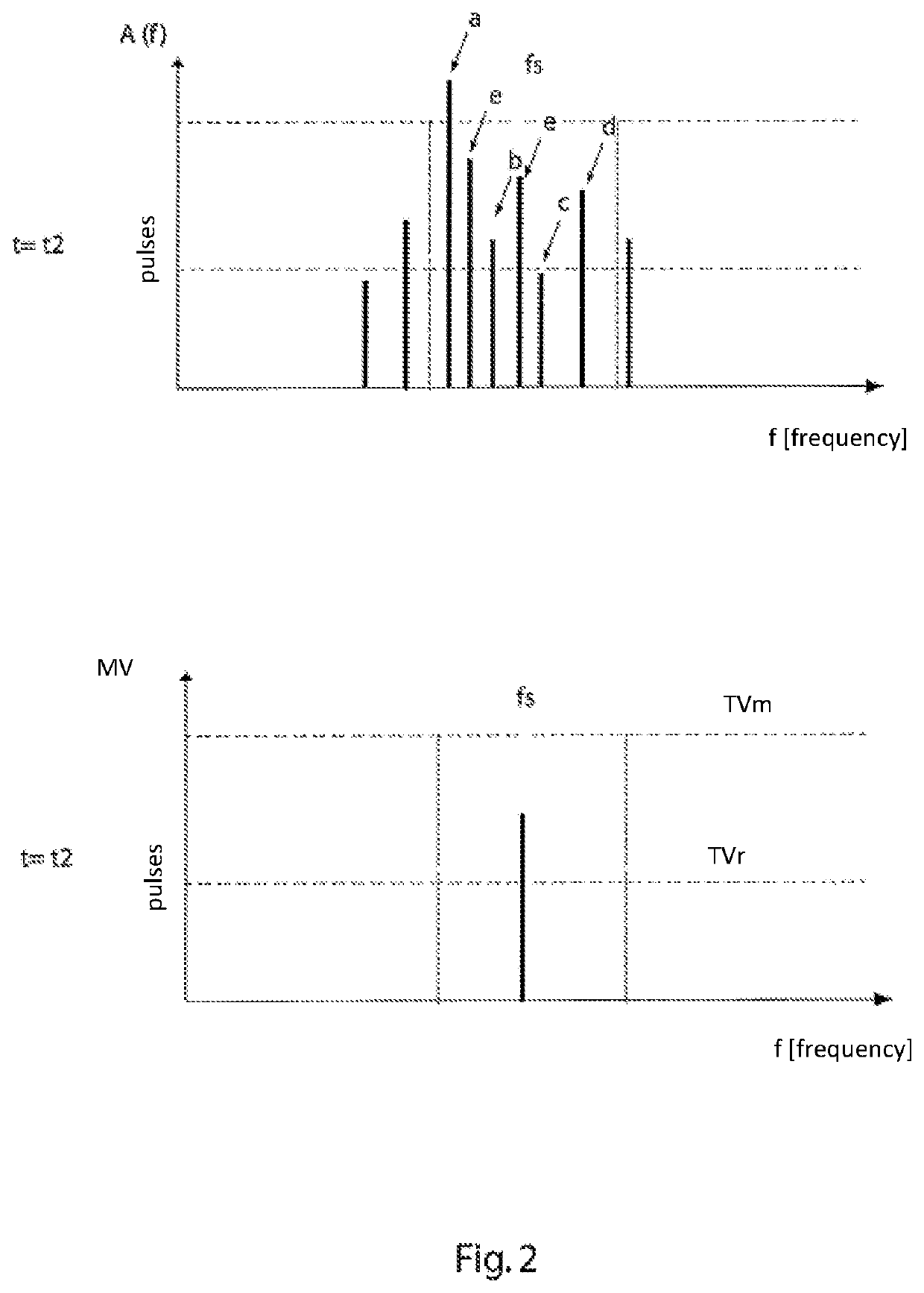
[0033]The FIGS. 1 and 2 each show a simplified graph of the spectral lines of a frequency spectrum A(f) with the amplitude A at a first time t=t1 and a later time t=t2. The spectral lines a, b, c, d are each meant to represent bearing damage in the rolling bearing 2 and present the respective amplitudes in the frequency spectrum. These are shown in the FIGS. 1 and 2 merely exemplary as discrete spectral lines. The degree of bearing damage is ascertained across the amplitude A. The higher the amplitude and the respective addition, the higher the bearing damage. Presently merely 7 such spectral lines from the (not represented) frequency spectrum are shown exemplary in FIG. 1, whereas in FIG. 2 additional damage was added exemplary (represented by the ...


PUM


Abstract

The present disclosure relates to a method and an apparatus for monitoring a rolling bearing of an electric motor, wherein the rolling bearing forms a capacitive parasitic antenna, having the following steps of: a. capturing the electromagnetic spectrum emitted by the parasitic antenna in a manner triggered by spark formation in the rolling bearing over a respectively defined period t during operation of the electric motor; b. evaluating the number N of electromagnetic pulses (a, b, c, d, e) received in the spectrum and the amplitude A of said pulses; c. capturing the change in the number N of electromagnetic pulses (a, b, c, d, e) and / or the amplitude A of said pulses, and d. determining whether the increase in the number N and / or in the amplitudes A of the electromagnetic pulses (a, b, c, d, e) increases in a non-linear manner with time.

Description

RELATED APPLICATIONS[0001]This application claims priority to German Patent Application No. 10 2017 125 890.6, filed Nov. 6, 2017, and PCT / EP2018 / 080012, filed Nov. 2, 2018, the entire contents of which are incorporated herein by reference in their entirety.FIELD[0002]The present disclosure relates to a method and an apparatus for monitoring rolling bearings in an electric machine such as an EC motor.BACKGROUND[0003]Nowadays, variable-speed motors are largely powered by intermediate circuit voltage converters. Powering an electric machine from a pulse-controlled inverter may for example form a capacitively coupled bearing voltage. The inverter switched pulse pattern results in a common mode voltage (CMV) jumping in accordance with the inverter switching frequency versus ground.[0004]Powering by the intermediate circuit voltage converter may therefore lead to undesirable bearing voltages, which in turn may lead to bearing currents in the motor bearings. Such a current flow through th...

Claims


Application Information

Patent Timeline
Patent Type & Authority Patents(United States)
IPC IPC(8): G01M13/04G01D5/244F16C19/06
CPCG01M13/04G01D5/244F16C19/06F16C2233/00F16C2380/26H02K7/083H02K15/00H02K11/35G01H9/00G01R31/343G01R31/001G01R29/0892G01R23/16
Inventor WYSTUP, RALPH
Owner EBM PAPST MULFINGEN GMBH & CO KG
Why Eureka
Try Eureka