Sealing assembly to fill and seal a reservoir or a disposable gas lighter

a gas lighter and reservoir technology, applied in the field of gas lighters, can solve the problems of brittleness of amorphous materials, poor cost effectiveness of such solutions, and remained the risk of cracking, so as to reduce the risk of fuel spillage. effect of supply

Active Publication Date: 2018-11-13
SOC DITE SOC BIC
View PDF23 Cites 0 Cited by
  • Summary
  • Abstract
  • Description
  • Claims
  • Application Information

AI Technical Summary

Benefits of technology

[0013]Thanks to these dispositions, it is possible to obtain an inexpensive and reliable solution to seal the reservoir of a disposable gas lighter or a gas reservoir for any type of lighter.
[0016]the weld portion may be formed as a frusto-conical portion, intended to be melted against an edge portion of the well; whereby the welding operation is facilitated;
[0018]the front portion, the bulge portion and the weld portion are arranged axially next to one another; thereby providing a compact solution in the axial direction;
[0019]the seal assembly is advantageously deprived of any intermediate part between the plug and the well, and deprived of any elastic member or biasing member; whereby the solution is particularly simple and the cost of the solution is especially low;
[0022]the plug can be integrally molded with the reservoir; thereby decreasing the cost of parts supply.
[0030]steps / B / and / C / may be performed with the help of an injection nozzle having a movable center rod, such that the movement from first position to second position can be performed without removing the injection nozzle just after the filling operation; thereby providing an optimized solution in order to minimize the spill of the fuel supply.

Problems solved by technology

However, such amorphous materials may be brittle as a result of their non-crystalline structure.
However, the force-fit introduction of the ball within the well can cause cracks in the well of the reservoir and thus create a leakage.
Other methods rely on the use of an 0-ring seal; however the cost effectiveness of such solutions is poor with regard to a definitive sealing feature.
Since such valve is force-fitted into the well, the risk of causing cracks remains.

Method used


Image

  • Sealing assembly to fill and seal a reservoir or a disposable gas lighter
  • Sealing assembly to fill and seal a reservoir or a disposable gas lighter
  • Sealing assembly to fill and seal a reservoir or a disposable gas lighter

Examples


Embodiment Construction

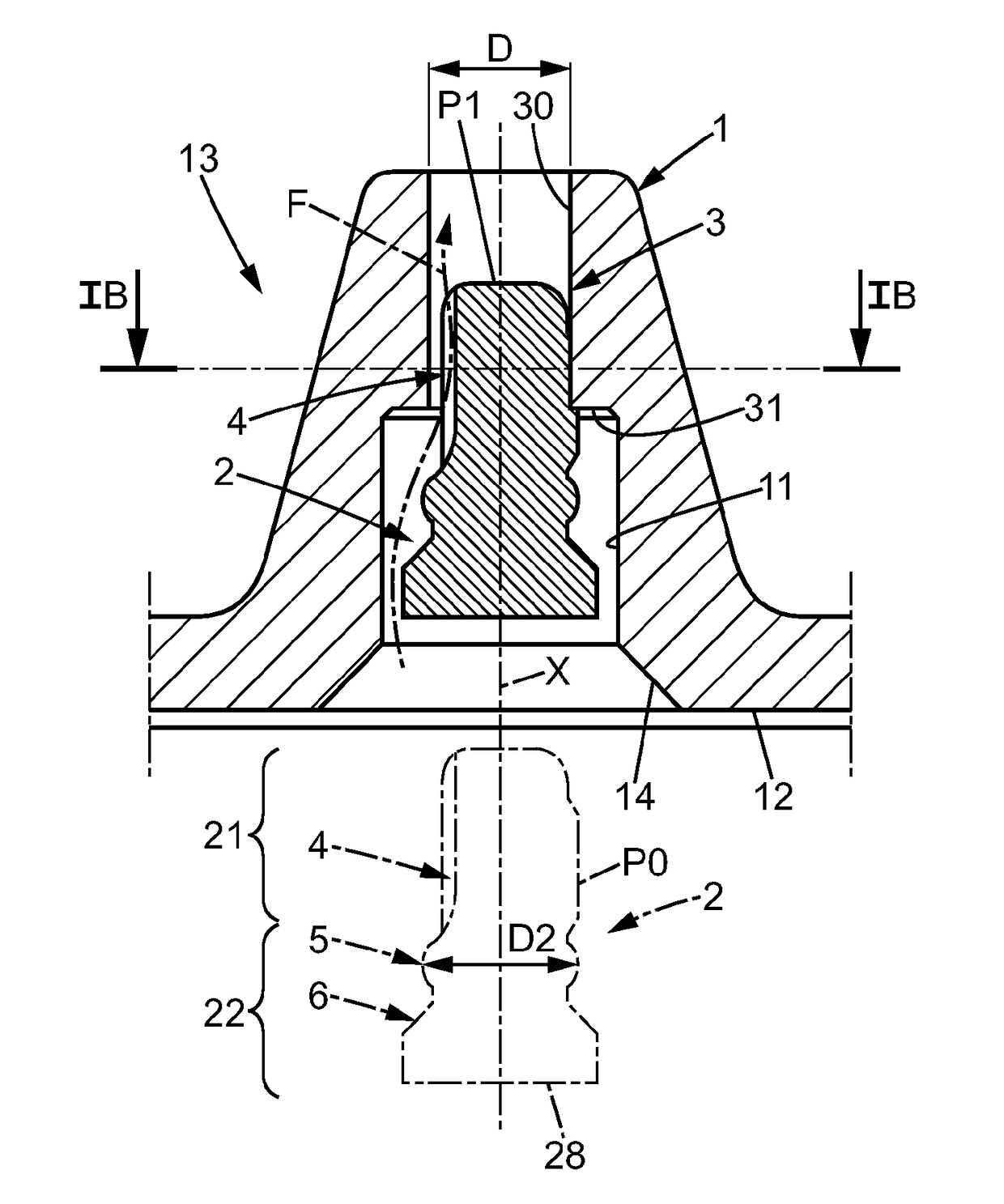
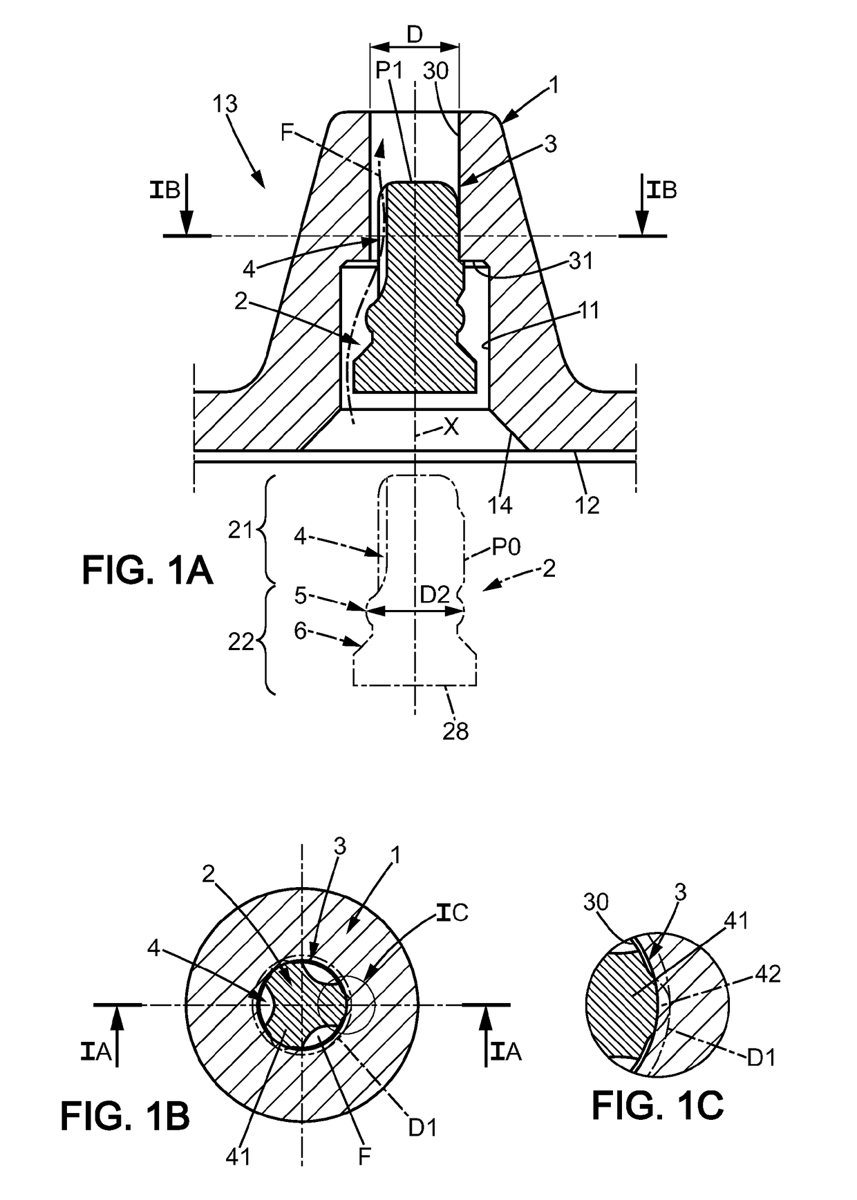
[0009]To this end, it is provided a sealing assembly, enabling to fill and seal a reservoir of a disposable gas lighter, comprising[0010]a substantially cylindrical well provided in the reservoir body, having an inner wall,[0011]a plug, intended to be received in the well, having a front section and a rear section, the front section comprising radial projections and at least one recess to provide a fluid passage, the rear section having a circular bulge portion, and a weld portion adapted to be melted by welding,

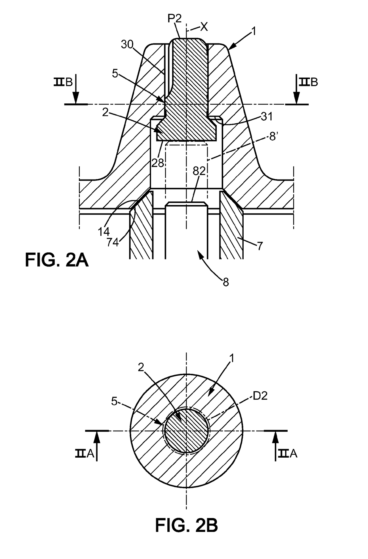
[0012]wherein the plug is adapted to be moved from a first axial position in which a passage is provided between an inner portion of the reservoir and outside, to a second axial position (P2) providing a temporary seal position in which a gastight contact is provided between the circular bulge portion of the plug and the inner wall of the well, and further from the second position to a third axial position (P3) providing a definitive seal position, wherein the weld portion o...


PUM

PropertyMeasurementUnit
diameteraaaaaaaaaa
diameteraaaaaaaaaa
diameteraaaaaaaaaa

Abstract

A sealing assembly, for filling and sealing a reservoir of a gas lighter that includes a cylindrical well, a plug having a front section and a rear section, the front section having radial projections and at least one recess to provide a fluid passage, the rear section having a circular bulge / bump portion, and a weld portion adapted to be melted by welding, wherein the plug is adapted to be moved from a first position (P1) in which a gas passage is, to a second position (P2), temporary seal position, in which a gastight contact is provided between the circular bulge portion of the plug and an inner wall of the well, and further from the second position to a third axial position (P3), definitive seal position, wherein the weld portion of the plug is definitely welded to the reservoir in a gastight manner.

Description

[0001]This application is a national stage application of International Application No. PCT / IB2013 / 000534, filed on Mar. 5, 2013, the entire contents of which are incorporated herein by reference.FIELD OF INVENTION[0002]The embodiments of the present invention relate to gas lighter, particularly a disposable gas lighter or gas reservoir for any type of lighter.BACKGROUND OF THE INVENTION[0003]More precisely, the embodiments of the present invention relates to a device and a method for facilitating the operations of filling and sealing of the lighter. More particularly the present invention relates to a disposable lighter or a gas reservoir for all types of lighter of the type which comprises a reservoir made of plastic material, especially amorphous plastic, adapted to be filled with a liquid hydrocarbon, especially butane or mixtures of butane and other hydrocarbons.[0004]Synthetic amorphous materials, like polymers such as ABS (Acrylonitrile Butadiene Styrene) or polycarbonate, of...

Claims


Application Information

Patent Timeline
Patent Type & Authority Patents(United States)
IPC IPC(8): F23Q2/52B65B7/28B65D39/00B65D53/06B65B3/12B65B51/22
CPCF23Q2/52B65B3/12B65B7/2821B65D53/06B65B51/225B65D39/0005B65B7/2842
Inventor LEFEBVRE, GUYLEFEBVRE, YANN
Owner SOC DITE SOC BIC
Why Eureka
Try Eureka