Strip lamp

a strip lamp and lamp body technology, applied in the field of strip lamps, can solve the problems of reducing light output efficiency, uneven illumination, glare problems, etc., and achieve the effects of reducing glare, improving light output efficiency, and reducing the setting of the light shield

Active Publication Date: 2021-09-07
SELF ELECTRONICS CO LTD +2
View PDF5 Cites 0 Cited by
  • Summary
  • Abstract
  • Description
  • Claims
  • Application Information

AI Technical Summary

Benefits of technology

[0005]In view of this, the present invention provides a strip lamp to solve the above technical problems. In particular it is an object of the present invention to provide a strip lamp of simple and cost-effective configuration enabling a uniform illumination.
[0024]In the strip lamp of the present invention, by arranging two opposing light source mounting seats in the strip light frame, the shielding of the light source mounting seats on the opposite side of the light source reduces glare, on the one hand, the setting of the light shield is reduced and the light output efficiency is improved. On the other hand, it also has a better anti-glare effect.

Problems solved by technology

Since the light-emitting effect of the LED chip cannot meet the lighting requirements, it is necessary to perform secondary optical design through lens coordination to meet specific light distribution requirements.
Therefore, the illumination is the smaller in the illumination area where the illumination distance is farther, resulting in an uneven illumination.
At this time, glare problems will occur.
Due to size issues, the anti-glare cover is generally set close, and the light output efficiency will decrease at this time.

Method used


Image

  • Strip lamp
  • Strip lamp
  • Strip lamp

Examples


Embodiment Construction

[0035]Hereinafter, specific embodiments of the present invention will be described in further detail based on the drawings. It should be understood that the description of the embodiments of the present invention is not intended to limit the protection scope of the present invention.

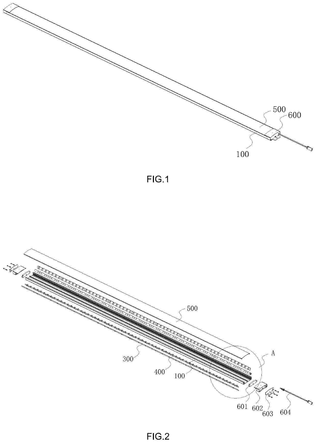
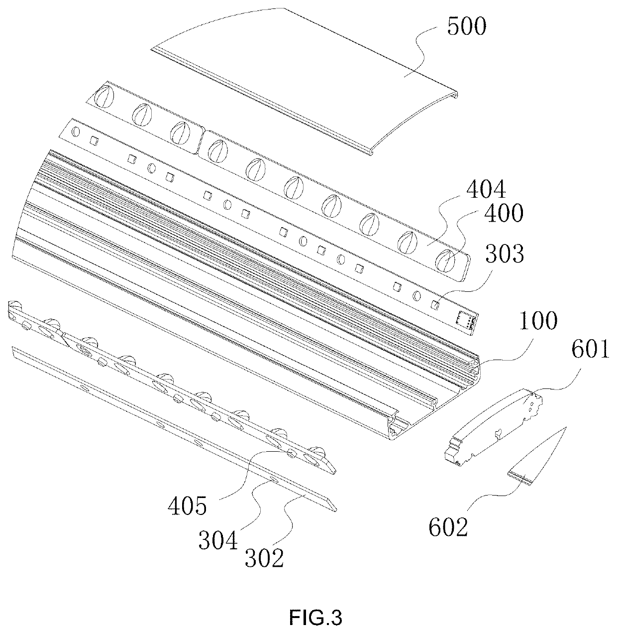
[0036]As shown in FIGS. 1 to 9, the strip lamp according to the present invention includes a strip lamp holder 100, two rows of light sources 300 and two lenses 400.

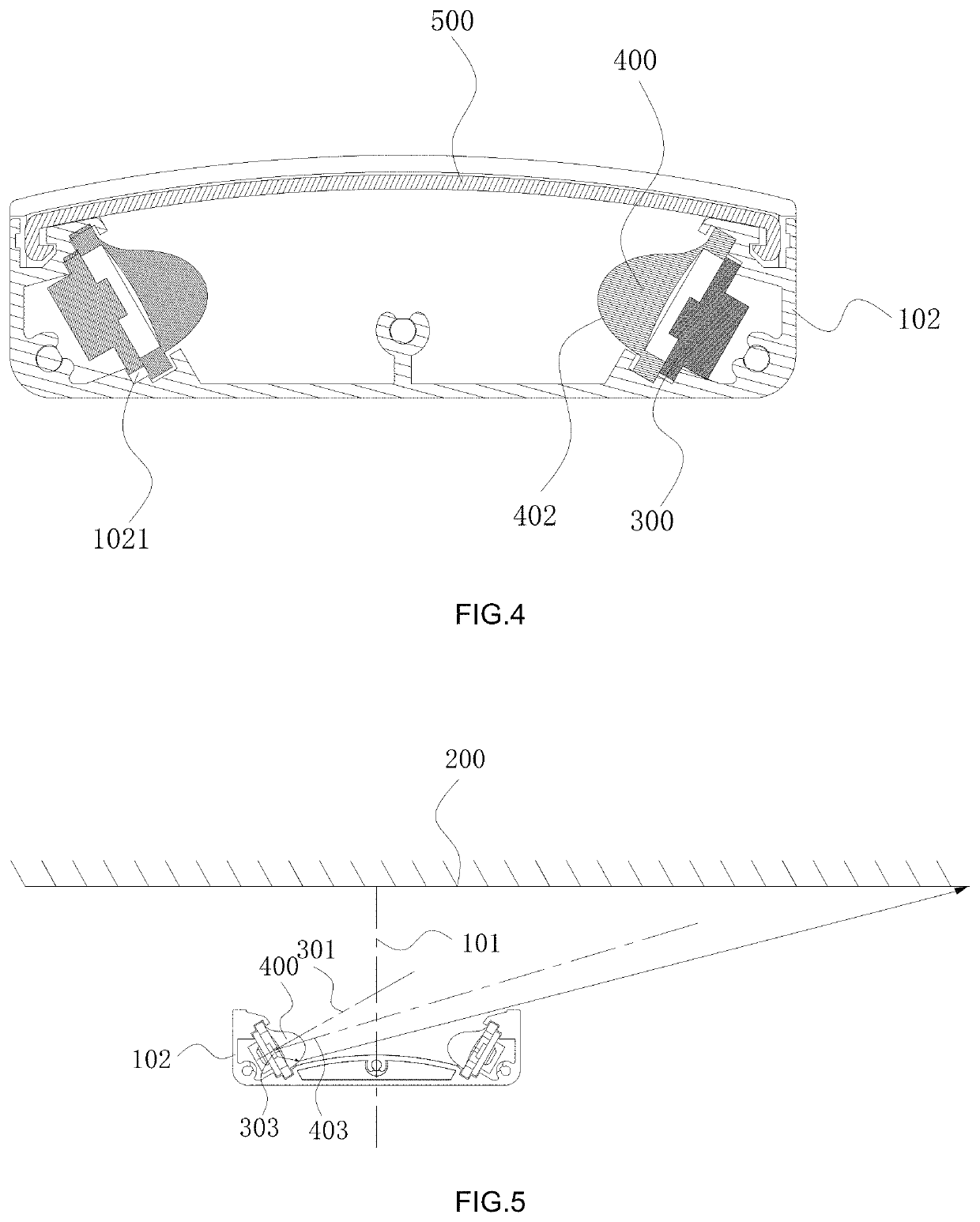
[0037]The strip lamp of the present invention is provided with light sources and lenses arranged along its length direction, and the main light distribution occurs in a plane perpendicular to its length direction. Therefore, the following content is mainly described based on this plane.

[0038]The strip lamp holder 100 has a center line 101 perpendicular to the illuminated surface 200 (the surface to be illuminated) in a plane perpendicular to its length direction. The strip lamp holder 100 is provided with two light source mounting seats 102 o...


PUM

PropertyMeasurementUnit
included angleaaaaaaaaaa

Abstract

A strip lamp includes a strip lamp holder, provided with two light source mounting seat oppositely arranged and located on both sides of the center line; two rows of light sources, respectively arranged on the two light source mounting seats, and the light emission directions are all toward the illuminated surface and the two optical axes intersect at or near the center line; two lenses, respectively arranged on a light source mounting seat and located in the light emission direction of the corresponding light source, and both include a light entrance surface and a light emission surface. The shielding of the light source mounting seats on the opposite side of the light source reduces glare, on the one hand, the setting of the light shield is reduced and the light output efficiency is improved. On the other hand, the strip lamp also has a better anti-glare effect.

Description

RELATED APPLICATION[0001]This application claims priority to a Chinese Patent Application No. CN 201911349454.9, filed on Dec. 24, 2019, the whole content of which is hereby incorporated by reference.FIELD OF THE TECHNOLOGY[0002]The present invention relates to the field of lighting fixtures, with particular emphasis on a strip lamp.BACKGROUND OF THE INVENTION[0003]Compared with traditional lighting lamps, LED lamps have the advantages of small size, low energy consumption and high light efficiency. Thus, LED lamps can be quickly promoted and applied. At the same time, people are constantly pursuing better lighting effects, so they also hope that LED lamps can meet various lighting needs. Especially when a large area is required to be illuminated, it is desirable to make the illumination of the illuminated area as uniform as possible. Since the light-emitting effect of the LED chip cannot meet the lighting requirements, it is necessary to perform secondary optical design through len...

Claims


Application Information

Patent Timeline
Patent Type & Authority Patents(United States)
IPC IPC(8): F21S4/28F21V1/14F21V5/00F21V5/04F21V13/02F21Y105/16F21Y103/10F21Y115/10
CPCF21S4/28F21V1/143F21V5/007F21V5/04F21V13/02F21Y2103/10F21Y2105/16F21Y2115/10F21S2/00F21V21/10F21V21/02F21V19/001F21V3/02F21V11/00
Inventor XUE, YUANFANGPAN, HUANGFENGZHU, QUANZHENG, ZHAOYONG
Owner SELF ELECTRONICS CO LTD
Why Eureka
Try Eureka