
Process for manufacturing a padding device for a carrying belt system for a respirator

a technology of carrying belt and padding device, which is applied in the field of manufacturing a padding device for a carrying belt system for a respirator, can solve the problems of affecting the drying process of this type of padding device or the corresponding carrying belt, the drying process is relatively long, and the moisture barrier is damaged by the sewing of the shell,

Active Publication Date: 2020-03-31
DRAGER SAFETY
View PDF21 Cites 0 Cited by
  • Summary
  • Abstract
  • Description
  • Claims
  • Application Information

AI Technical Summary

Benefits of technology

The solution simplifies and cost-reduces the manufacturing of padding devices, enhances comfort and durability, and facilitates quick drying and decontamination by eliminating seams and using a seamless, elastomer-based design.

Problems solved by technology

However, as one drawback, it was found that the moisture barrier is damaged by the sewing of the shell, as a result of which moisture can penetrate between the elastic core and the textile shell.
Consequently, the drying process for this type of padding device or for the corresponding carrying belt lasts for a relatively long time.
In the case of a contamination, it is further not possible or only possible with extreme difficulty to remove all harmful substances without residues from an area between the elastic core and the textile shell.
Such padding devices or corresponding carrying devices have, however, a complicated configuration consisting of many individual parts.

Method used


Image

  • Process for manufacturing a padding device for a carrying belt system for a respirator
  • Process for manufacturing a padding device for a carrying belt system for a respirator
  • Process for manufacturing a padding device for a carrying belt system for a respirator

Examples


first embodiment

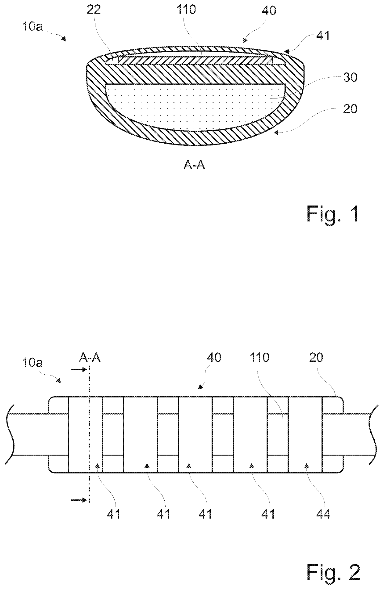
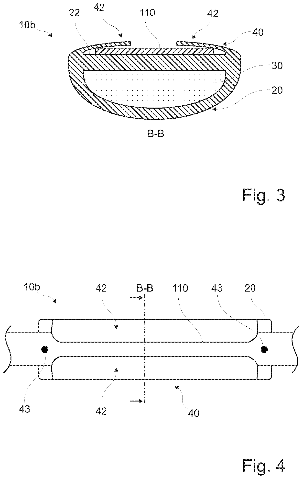
[0052]FIG. 1 shows a sectional view of a padding device 10a for a carrying belt system 100 according to a The padding device 10a has a closed pad core shell 20 and a pad core 30 arranged in the pad core shell 20. The pad core shell 20 shown in FIG. 1 is configured as a seamless, injection-molded component. A belt strap connection device 40 is connected in one piece to the pad core shell 20 according to FIG. 1, i.e., the belt strap connection device 40 is configured as an integral component of the pad core shell 20. The belt strap connection device 40 and the pad core shell 20 together form a ring section 41, through which a belt strap 110 runs and in which the belt strap 110 is arranged. The belt strap connection device 40 is provided on an outer side 22 of the pad core shell 20 according to FIG. 1. This is shown in a top view in FIG. 2 for a better understanding of the padding device 10a.

[0053]FIG. 3 shows a sectional view of a padding device 10b for a carrying belt system 100 ac...

third embodiment

[0056]FIG. 9 shows the padding device 10c in another sectional view. As shown in FIG. 9, the pad core shell 20 has a plurality of pad core chambers 23, wherein a pad core 30 is configured in each of the pad core chambers 23.

[0057]FIG. 10 shows a respirator 1000 with a carrying belt system 100. The respirator 1000 further has a respirator functional unit rear part 1010, on which or to which functional units of the respirator 1000 can be mounted. The respirator 1000 shown in FIG. 10 has four padding devices 10a. The respirator 1000 shown in FIG. 10 represents a closed-circuit respirator.

[0058]Subsequently, a process for manufacturing a padding device 10e according to a fifth embodiment is described with reference to FIGS. 11 through 14. The padding device 10e according to the fifth embodiment represents an especially simple manner of configuration of a padding device according to the present invention.

[0059]According to the process shown in FIGS. 11 through 14, in a first step, which...


PUM

PropertyMeasurementUnit
timeaaaaaaaaaa
areaaaaaaaaaaa
resistanceaaaaaaaaaa

Abstract

A process manufactures a padding device (10a; 10b; 10c; 10d; 10e), for a carrying belt system (100) for a respirator (1000), having a closed pad core shell (20) and a pad core (30) configured in the pad core shell. The process includes injection molding a hollow profiled section, inserting of a pad core material into the hollow profiled section for forming the pad core in the hollow profiled section, and closing the hollow profiled section (21) for creating the closed pad core shell (20). The padding device (10a; 10b; 10c; 10d; 10e) has a closed pad core shell (20) and a pad core (30) arranged in the pad core shell. The pad core shell is seamless as an injection-molded component in at least some sections. A carrying belt system as well as a respirator with the carrying belt system are provided with the belt system having the padding device.

Description

CROSS REFERENCE TO RELATED APPLICATIONS[0001]This application claims the benefit of priority under 35 U.S.C. § 119 of German Patent Application 10 2016 004 311.3, filed Apr. 12, 2016, the entire contents of which are incorporated herein by reference.FIELD OF THE INVENTION[0002]The present invention pertains to a process for manufacturing a padding device for a carrying belt system for a respirator. The present invention further pertains to a padding device for a carrying belt system for a respirator, having a closed pad core shell and a pad core arranged in the pad core shell. In addition, the present invention pertains to a carrying belt system as well as to a respirator with the carrying belt system, the carrying belt system having the padding device.BACKGROUND OF THE INVENTION[0003]Padding devices and carrying belt systems for respirators are known in the state of the art. Carrying belt systems for respirators have to have a high resistance, because they are exposed to the highes...

Claims


Application Information

Patent Timeline
Patent Type & Authority Patents(United States)
IPC IPC(8): B29C45/14A62B25/00A45F3/00B29C71/02B29C57/10B29C44/18A45F3/12B29D99/00B29C44/08B29K67/00B29K75/00B29K105/04B29L9/00B29L22/00B29L31/58
CPCB29D99/0092B29C71/02B29C45/14622B29C44/18A62B25/00A45F3/005A45F3/12B29C57/10B29K2075/00B29L2009/00B29L2022/00B29K2105/04B29L2031/58B29C44/08A45F2003/127B29K2067/00
Inventor WILKE, BASTIAN
Owner DRAGER SAFETY
Learn More