Stator of an electric machine

a technology of electric machines and stabilizers, which is applied in the direction of windings, dynamo-electric components, insulation materials of windings, etc., can solve the problems of inability to insert as many windings, inability to achieve the effect of high operational reliability, and limiting the achievable copper filling factor of methods, etc., to achieve simple and cost-effective manufacturing and high operational reliability.

Inactive Publication Date: 2011-09-01
ROBERT BOSCH GMBH
View PDF8 Cites 20 Cited by
  • Summary
  • Abstract
  • Description
  • Claims
  • Application Information

AI Technical Summary

Benefits of technology

[0004]Embodiments of the present invention provide a stator of an electric machine which, having coils wound outside of the stator, achieves a maximum degree of copper filling and, thus, a maximum magnetic flux density, thus ensuring a simple and cost-effective manufacture combined with a very high operational reliability. Embodiments of the present invention provide a stator of an electric machine having at least one stator tooth and a coil wound outside of the stator, which is slid onto the stator tooth essentially radially. Embodiments of the present invention have a provision for the coil to be retained radially on the stator sooth by at least one positive engagement. The coil wound outside of the stator, which is mounted onto the stator tooth as a prefabricated component, is radially retained on the stator tooth by at least one positive engagement. In embodiments, the coil wound outside of the stator is radially retained on the stator tooth by at least one positive engagement in such a way that it cannot slide off the stator tooth onto which it was slid.

Problems solved by technology

This method considerably limits the achievable copper filling factor.
That is, it is not possible to insert as many windings as are possibly required in order to reach a certain magnetic flux or a certain magnetic field density.
This manufacturing method is very painstaking and susceptible to production errors.
This described situation involves a very complicated and error-prone coil winding process, because the required coil geometry must be met very precisely, otherwise mounting onto the stator teeth is not possible or is possible only by impairing the coil geometry, which in the original case ends in the destruction of the coil.
The failure of a coil in this case entails practically with necessity the failure of the adjacent coil as well.

Method used


Image

  • Stator of an electric machine
  • Stator of an electric machine
  • Stator of an electric machine

Examples


Embodiment Construction

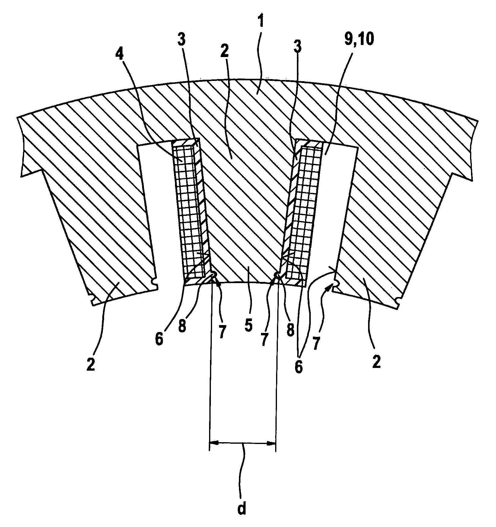
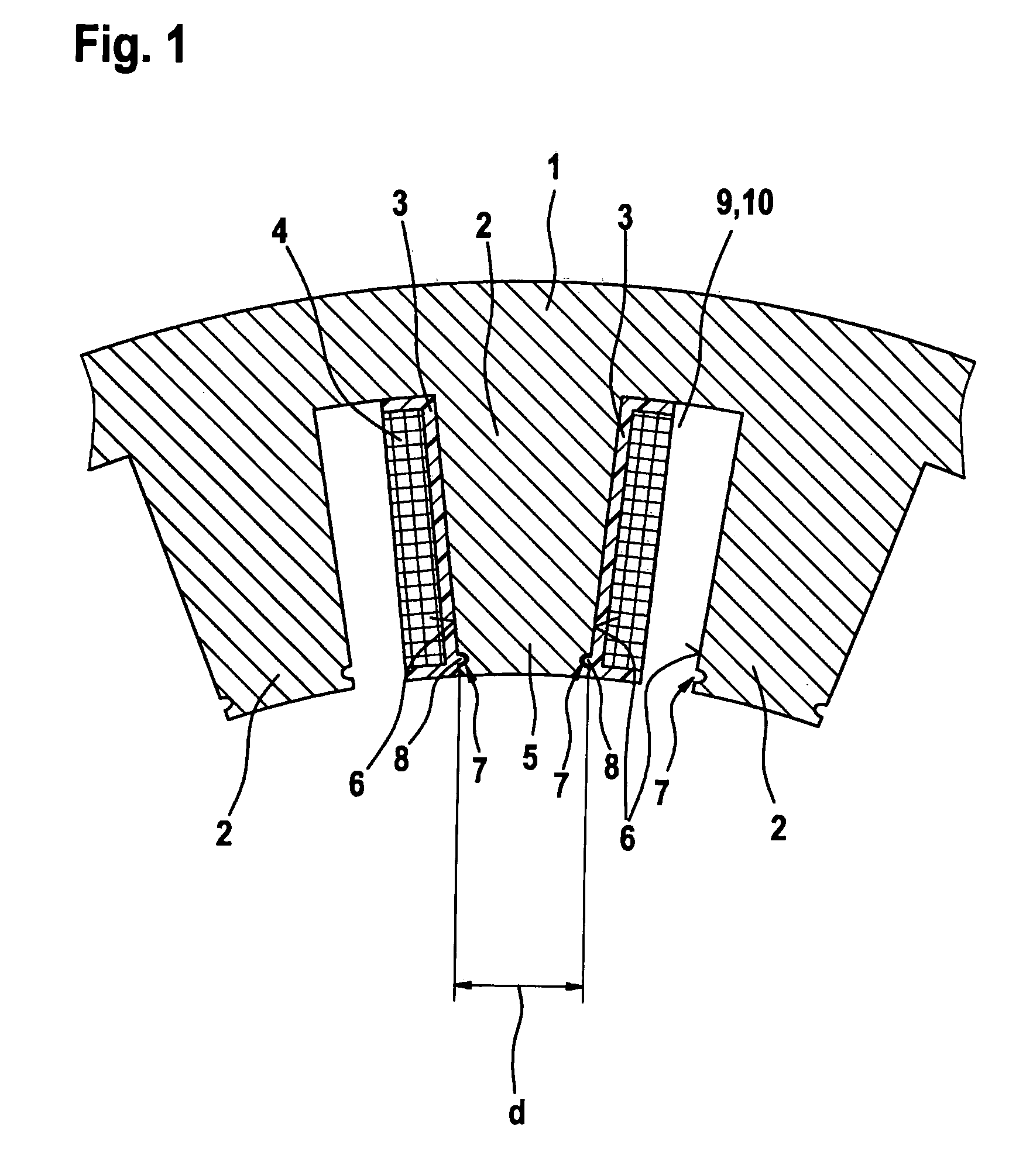
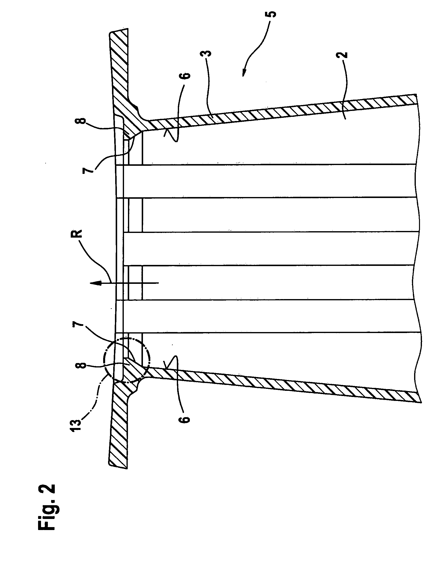
[0019]FIG. 1 shows a cross-sectional view of a segment of a hollow stator 1 of an electric machine (not shown) of an example embodiment of the present invention. Stator 1 has stator teeth 2 on its inner side, onto which a bobbin 3 is slid entirely, its longitudinal orientation being essentially identical to that of stator tooth 2. Bobbin 3 bears a coil 4. In an embodiment, bobbin 3 bears a coil 4 wound outside of the stator onto bobbin 3. In an embodiment, bobbin 3 is formed so as to embrace stator tooth 2 entirely on all sides. In an embodiment, it is developed in the form of bobbins known from other areas of the art, with the provision that its inner geometry is adapted to the geometry of stator tooth 2 in such a way that it may be slid entirely onto stator tooth 2. In am embodiment, in its head region 5, stator tooth 2 has on opposite tooth faces 6 respectively an undercut 7 into which a latch 8 engages, which is formed on the inner side on bobbin 3, in such a way that it reaches...


PUM


Abstract

The invention relates to a stator of an electrical machine, with at least one stator tooth and a coil wound outside of the stator, which coil has been pushed onto the stator tooth substantially radially. It is provided that the coil (4) is held radially on the stator tooth (2) by means of at least one form-fitting connection (13). Furthermore, the invention relates to an electrical machine with such a stator (1).

Description

FIELD OF INVENTION[0001]The present invention relates to a stator of an electric machine.BACKGROUND INFORMATION[0002]Stators of electric machines in principle may be wound in two ways. The windings are applied one after the other onto insulated individual stator teeth, or, alternatively, coils wound outside of the stator are fit onto teeth of the stator. If the coils are wound directly onto the stator teeth, their windings have to be prevented from slipping off the stator teeth. This is achieved, for example, by relying on the situation that the stator teeth have a greater cross section in their head region than in their root region in order thus to fix the coil windings on the tooth. This method considerably limits the achievable copper filling factor.[0003]That is, it is not possible to insert as many windings as are possibly required in order to reach a certain magnetic flux or a certain magnetic field density. In another development of this manufacturing method, the coil winding...

Claims


Application Information

Patent Timeline
Patent Type & Authority Applications(United States)
IPC IPC(8): H02K3/34
CPCH02K1/146H02K3/30H02K2203/12H02K3/522
Inventor ELSER, ARMIN
Owner ROBERT BOSCH GMBH
Why Eureka
Try Eureka