
Electronic control device

a control device and electronic technology, applied in the direction of electrical apparatus construction details, electrical apparatus casings/cabinets/drawers, lighting and heating apparatus, etc., can solve the problems of large volume within the control device, complex shielding, etc., and achieve the effects of small space, simple and cost-effective manufacture and installation, and small and compact design

Inactive Publication Date: 2015-01-06
ROBERT BOSCH GMBH
View PDF21 Cites 24 Cited by
  • Summary
  • Abstract
  • Description
  • Claims
  • Application Information

AI Technical Summary

Benefits of technology

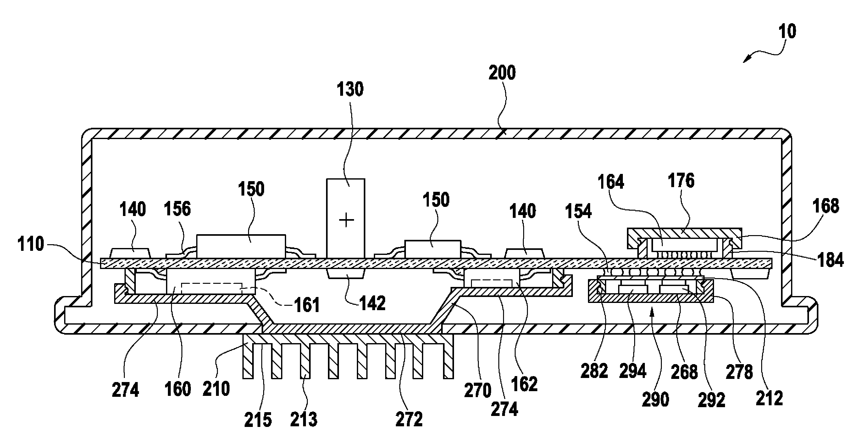
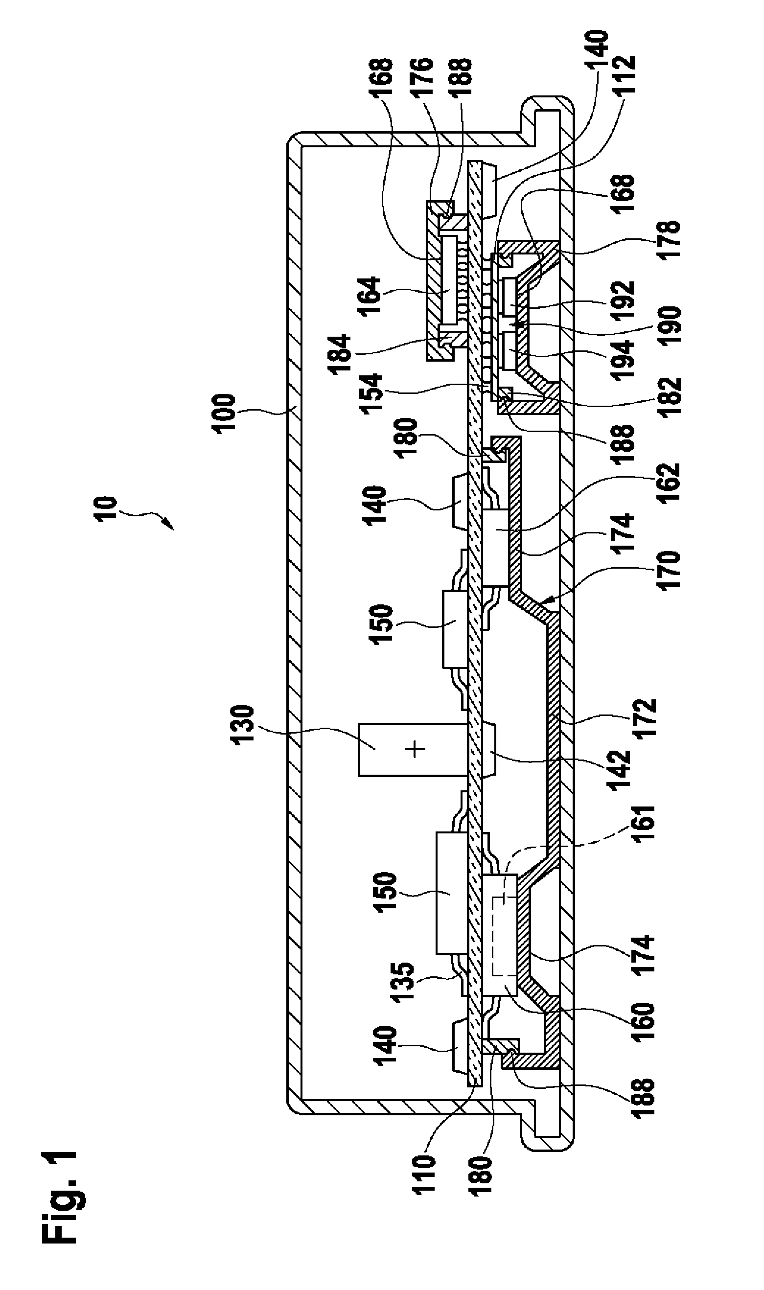
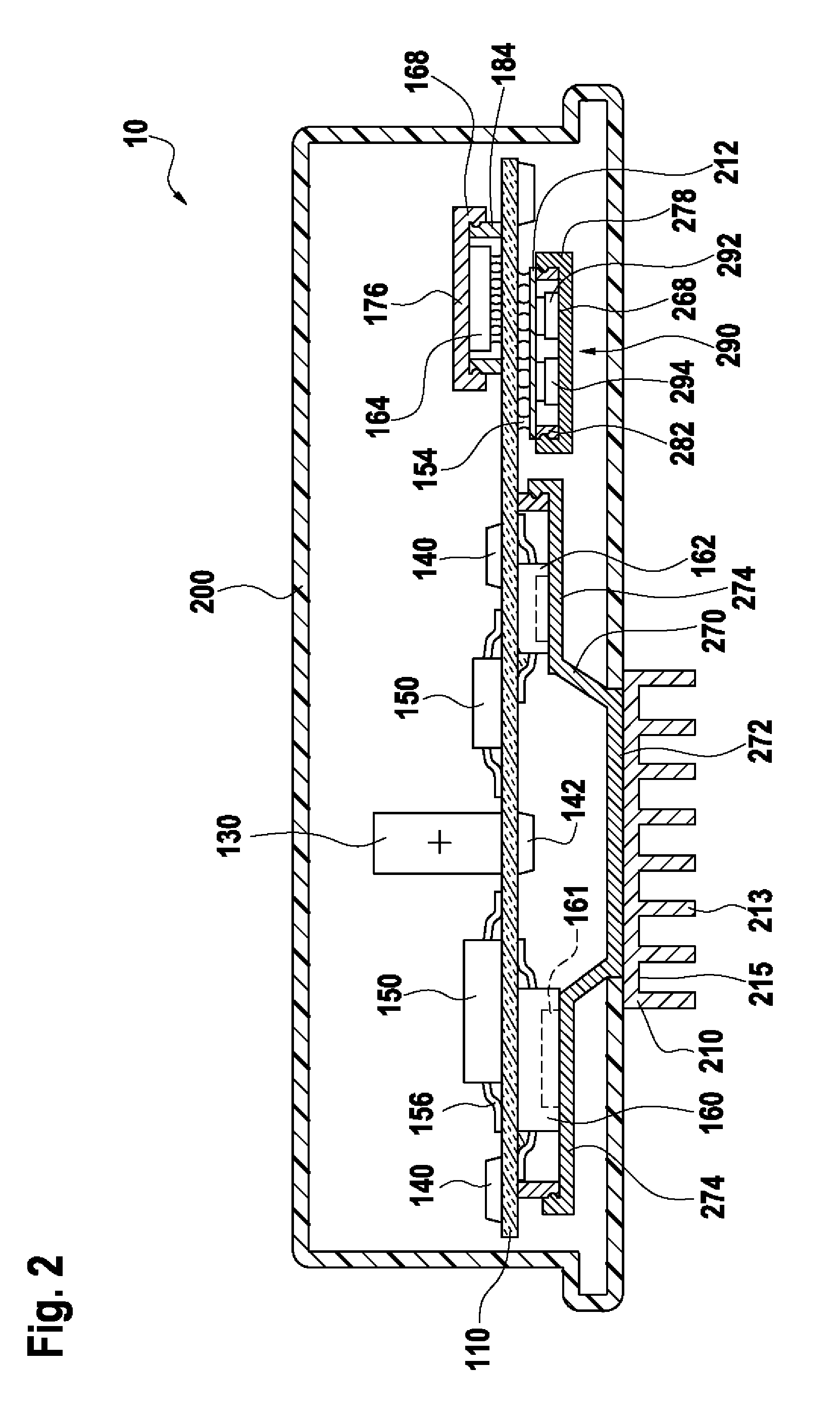
[0003]The control device according to the invention solves the problem of shielding from electrical and / or magnetic fields by the use of one or a plurality of electrically conductive shielding elements, which in each case together with the circuit board and possibly further components form a Faraday cage around the entire circuit, groups of components or individual components. By a Faraday cage, a casing closed to all sides or provided with openings is understood, the interior of which is shielded at low frequencies from external electrical fields or electromagnetic waves. For that purpose, an electrically conductive shielding element is manufactured, for example, from sheet metal or wire mesh. Such an electrically conductive shielding element is simple and cost effective to manufacture and to install and requires little space within the housing, and therefore a small and compact design is possible.
[0006]In circuits currently used for control devices, components in the so-called wafer level package design or flip-chip design are used. In order to prevent malfunctions of these components due to parasitic substrate currents, ground potential should be applied to the backside of the respective component in order to minimize potential shifts within the component. In order to facilitate the connection to ground potential, such components can have a metallic layer on the backside thereof. By a corresponding connection of the electrically conductive shielding element, on the one hand to this backside metallization of the component and on the other hand to ground potential, for example by means of corresponding contacts on the circuit board, the ground connection of the wafer level package component can be simply ensured without additional expense and effort. If the component does not have any backside metallization, the ground contact can nevertheless be made by means of a connection of the backside of the component to the electrically conductive shielding element which is as extensive as possible.

Problems solved by technology

The problem of shielding electronic components from electrical and / or magnetic fields occurs in many areas when using such control devices.
Such a shielding is however complex and requires large volumes within the control device.

Method used


Image

  • Electronic control device
  • Electronic control device
  • Electronic control device

Examples


Embodiment Construction

[0013]A housing 100 for a control device 10 is depicted in FIG. 1, which in this example is made from metal. The housing 100 is self-contained due to at least one cover or plug that is not depicted. A circuit board 110 is disposed in the housing 100. In this exemplary embodiment, the circuit board 110 is equipped with electrical and / or electronic components on both sides. In this case, the electrical and / or electronic components can relate, for example, to passive components, such as the capacitor 130 or resistors 140, 142, or to active components, for example the power components 150, 160, 162, 164, 192, 194. The components are, for example, contacted to the conducting paths running on the circuit board, which are not visible in the drawing, by means of lateral connections 135 or by balls of solder 154 or are connected to the circuit board, as in the example of the capacitor 130, via through connections that are not depicted.

[0014]A capacitor 130, resistors 140 as well as power com...


PUM


Abstract

The invention relates to an electronic control device (10) having electronic components (160, 162) on a circuit board (110) which are shielded from electrical and / or magnetic interference fields. According to the invention, an electrically conductive sheet metal part (170) is arranged on the circuit board (110) which forms a Faraday cage for the electronic components (160, 162) with the circuit board. The electrically conductive sheet metal part (170) is furthermore in thermal contact to the electronic components (160, 162) and in thermal contact to the housing (100) of the control device (10) and thereby deflects heat from the electronic components (160, 162) into the housing (100).

Description

BACKGROUND OF THE INVENTION[0001]The invention relates to a control device for providing electrical and / or magnetic shielding. Such devices are known in a variety of embodiments and for various applications. The problem of shielding electronic components from electrical and / or magnetic fields occurs in many areas when using such control devices. It is therefore necessary to protect the electronic circuit, parts thereof or also only individual components from electrical and / or magnetic stray radiation. It can similarly be necessary not to allow stray radiation originating in an electronic circuit to travel to the outside. It can also be further necessary to protect interference-sensitive components of the circuit from the radiation of interference emitting components of this circuit. Particularly control devices in motor vehicles have to therefore be improved with respect to the electromagnetic compatibility (EMC) thereof.[0002]The German patent publication DE 43 17 469 A1 discloses ...

Claims


Application Information

Patent Timeline
Patent Type & Authority Patents(United States)
IPC IPC(8): H05K7/20H01L23/552H01L25/16H05K9/00
CPCH05K9/0022H01L23/552H05K7/20418H05K7/20854H01L25/16H01L2924/0002H01L2924/00
Inventor WEEBER, VOLKERBARTH, HEINRICHSCHERTLEN, RALPH
Owner ROBERT BOSCH GMBH
Learn More