
Weapon mountable illumination device

a technology of illumination device and weapon, which is applied in the direction of electric lighting with batteries, light and heating apparatus, weapons, etc., can solve the problems of affecting the weight and balance of weapons, affecting the safety of operators, and casting shadows on the opposite side, so as to reduce the visual acuity of fellow operators, prevent inadvertent turning, and mitigate accidental actuation

Active Publication Date: 2021-09-07
IN EXTREMIS DESIGN & DEV LLC
View PDF70 Cites 2 Cited by
  • Summary
  • Abstract
  • Description
  • Claims
  • Application Information

AI Technical Summary

Benefits of technology

The present invention provides a weapon-mounted illumination device that offers lighting without creating shadows. The device has a streamlined form that is integrated with the weapon, making it easy to operate without getting snagged. Additionally, the illumination device is designed to be neutrally buoyant, meaning it doesn't affect the buoyancy of the weapon and accessories when used in water-based operations.

Problems solved by technology

Due to the placement of the flashlight on the side of the weapon, this can result in the casting of a shadow on the opposite side of the barrel from where the flashlight is mounted.
A shadow in low-light operations can result in a potential target or threat being obscured from illumination, thus creating a potentially life-threatening situation for the operator.
Although this decreases the casting of shadows, this results in negatively affecting the weapon's weight and balance.
Resultantly, the operator's ability to accurately engage targets is also negatively affected.
Furthermore, the mounting of a flashlight toward the muzzle-end of a weapon creates a protuberance which can result in the snagging or catching of the weapon on obstacles including, but not limited to, communication cords, pistol lanyards, seatbelts, wires, or other cable-like lines present in military and / or law enforcement vehicles, boats, and aircraft.
The positioning of a standard external flashlight is such that the vehicle seatbelt or harness will likely clear the barrel of the gun, but grab the light fixture, causing not only a delayed exit, but more importantly a negative impact to the operator's ability to accurately engage threats.
Operators have reported incidents of weapon-mounted flashlights catching on obstacles during ship-boarding operations, close-quarters combat operations, room-clearing operations, and during rappelling operations from buildings or fast-rope operations from helicopters.
An operator catching their weapon in any operation can pose a life-threatening risk.
For instance, during a rappelling or fast-rope operation, the catching of one's weapon can result in an uncontrolled fall from heights in excess of 40 feet.
The problem with such solutions surrounds the percussion and heat associated with the repeated firing of the firearm.
The percussion and heat adversely affect the performance of the lighting device, as well as the operation of the weapon.
The side-mounting of a flashlight to the forward aspect of a weapon may negatively affect the intended operation of the weapon due to imbalance and result in weapon malfunction.

Method used


Image

  • Weapon mountable illumination device
  • Weapon mountable illumination device
  • Weapon mountable illumination device

Examples


Embodiment Construction

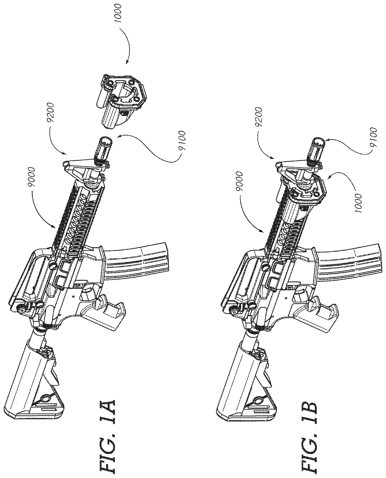
[0041]Certain embodiments of the present invention, such as shown in FIG. 1A-FIG. 1B, comprise a weapon mountable illumination device 1000 configured to slidably affix to the forward end of a firearm 9000 for providing illumination toward a forward 9100, or muzzle end, of the firearm 9000.

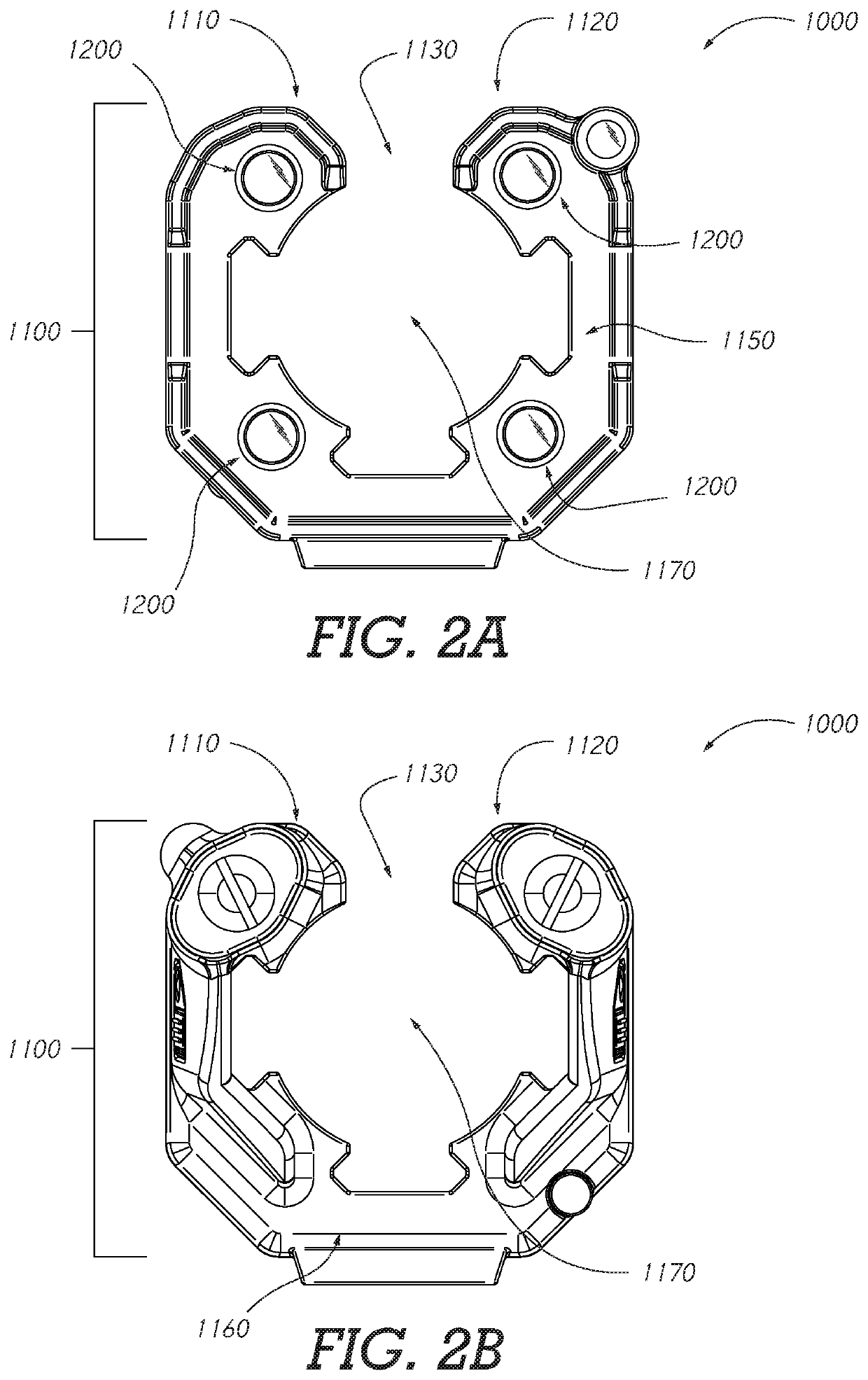
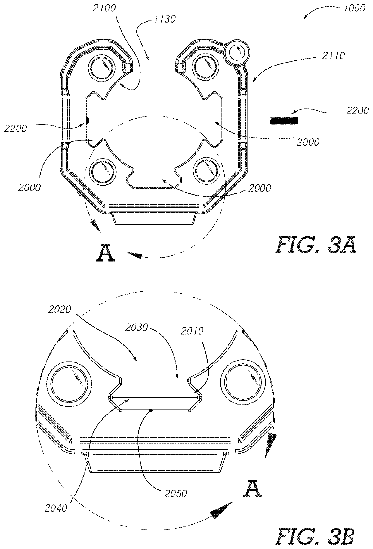
[0042]Certain embodiments comprise a weapon mountable illumination device 1000, as seen in FIG. 2A-FIG. 2B, which has a cuff form 1100 wherein the cuff form has a first end 1110, a second end 1120, and a gap 1130 disposed therebetween. The weapon mountable illumination device 1000 comprises a first open side 1150, a second open side 1160, and a pathway 1170 there between. The gap 1130 of the cuff form is configured to allow the mounting to a firearm 9000, now referencing FIG. 1A-FIG. 1B, without impediment to or from existing elements of the firearm such as fixed iron sights 9200 or backup iron sights (BUIS), a slide of a semi-automatic pistol, or other aspects, or accessories mounted to a top aspe...


PUM

PropertyMeasurementUnit
heightsaaaaaaaaaa
perimeteraaaaaaaaaa
internal perimeteraaaaaaaaaa

Abstract

A weapon mountable illumination device configured to mount to existing firearm mounting rails to provide illumination of potential targets while mitigating problems associated with snagging, and shadow casting. It is an aspect of the present invention to provide a rapidly mountable device to provide increased lighting capability while obviating the need to remove back up iron sights.

Description

FIELD OF THE INVENTION[0001]The present invention is directed to a weapon mountable illumination device which is intended to provide a modular and mobile lighting solution which mitigates problems associated with snagging, shadow casting, imbalance associated with the mounting to a weapon, and overheating of elements.BACKGROUND OF THE INVENTION[0002]In the conduct of law enforcement and military operations, weapon-mounted tactical lighting has become mission critical equipment in most operations wherein such equipment provides a high level of value in achieving success in a given operation.[0003]Handheld tactical lighting, generally used with pistols, requires the use of one hand to operate the weapon while the other hand of the operator is used to illuminate targets or areas of interest beyond the muzzle-end of the weapon.[0004]Weapon-mounted lighting, commonly used with long guns (shotguns, rifles, carbines, and other longer barreled firearms) allows the use of both hands in opera...

Claims


Application Information

Patent Timeline
Patent Type & Authority Patents(United States)
IPC IPC(8): F41G1/35F41G11/00F41H13/00
CPCF41G11/003F41G1/35F41H13/0056F41C27/00F21L4/02F41G1/34F41G11/004
Inventor NEEL, RYANDEBOBES, DENNISJAKUBOWSKI, JEFFREY
Owner IN EXTREMIS DESIGN & DEV LLC
Learn More