Centrifuge with linear drive

a technology of centrifuge and drive, which is applied in the field of centrifuge, can solve the problems of not always very easy to carry out work steps, not always easy to automate individual laboratory activities, and not only an additional source of errors in the transport of components

Active Publication Date: 2021-09-14
BLUECATBIO GMBH
View PDF28 Cites 4 Cited by
  • Summary
  • Abstract
  • Description
  • Claims
  • Application Information

AI Technical Summary

Benefits of technology

[0011]An object of the present invention is to provide a centrifuge comprising a loading and unloading device which allows precise maneuvering of a reaction vessel unit into and out of the rotor chamber. Another task of the present invention is to provide a centrifuge with which complex process steps can be carried out in the smallest possible space.

Problems solved by technology

The automation of individual laboratory activities is nowadays almost unavoidable.
However, it is not always very easy to carry out work steps that require very precise handling of individual test components by automated devices.
This poses the challenge of precisely matching both the vessel and the pipette.
Transporting the components is not only an additional source of error, for example due to contamination, but also takes additional time.

Method used


Image

  • Centrifuge with linear drive
  • Centrifuge with linear drive
  • Centrifuge with linear drive

Examples


Embodiment Construction

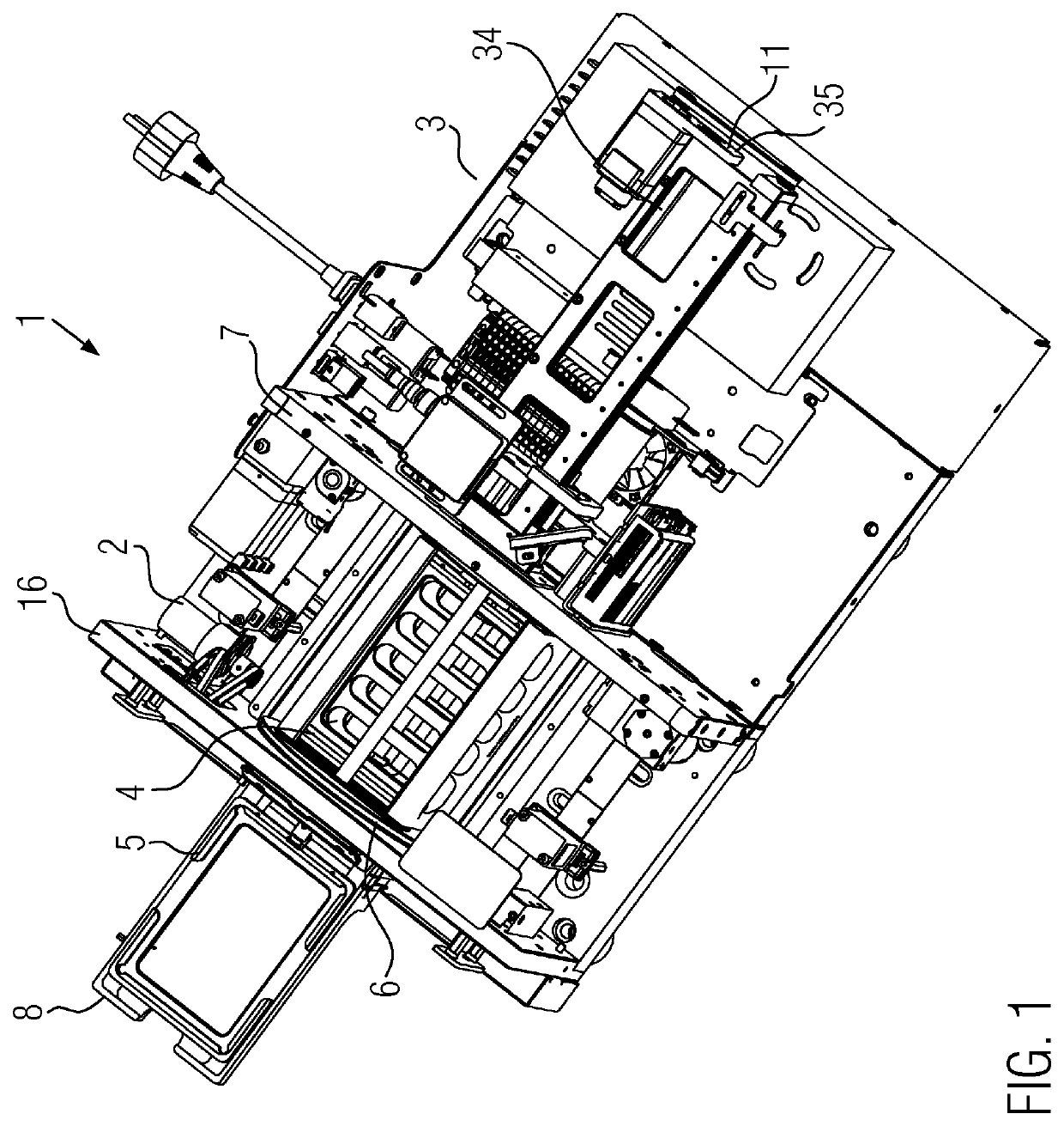
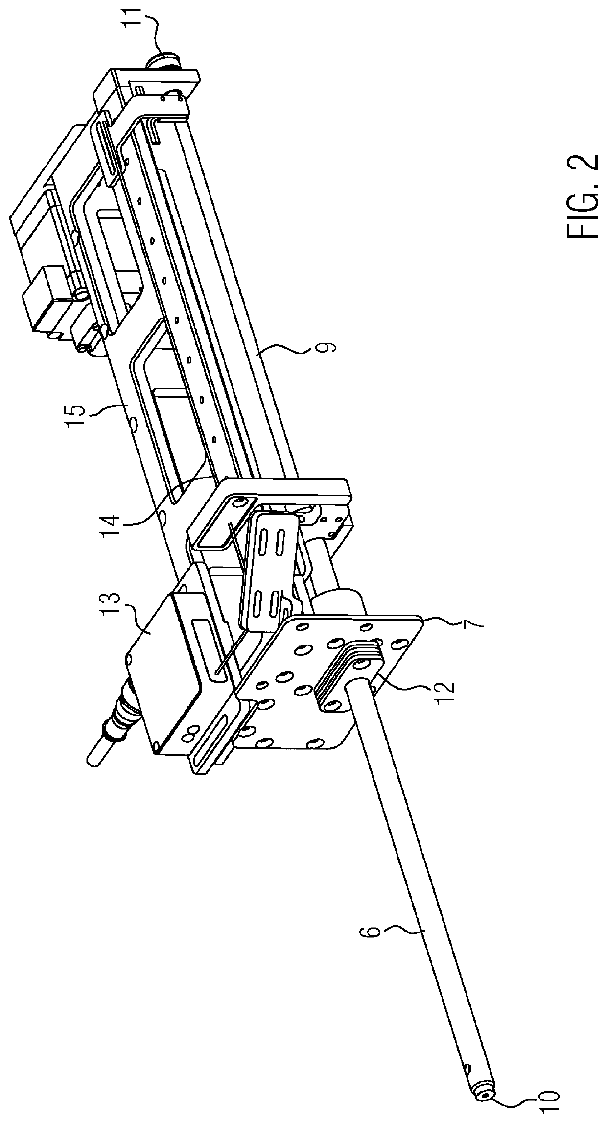
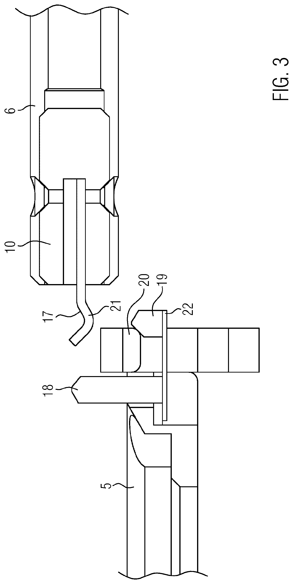
[0102]In the following, a design example of an ingenious centrifuge 1 is explained in more detail. This centrifuge 1 comprises a rotor chamber 2, in which the rotor 4 is located, a drive unit 3, in which a linear drive 11 and a sliding rod 6 are arranged. Using the sliding rod 6, a reaction vessel unit or a support unit 5 for a reaction vessel unit can be pulled into rotor chamber 2 or pushed out of the rotor chamber onto a balcony 8 (FIG. 1).

[0103]Rotor 4, which can be loaded with at least one reaction vessel unit, can be found in rotor chamber 2 and can rotate about an axis of rotation. Preferably the rotor 4 rotates around a horizontal axis of rotation.

[0104]Rotor chamber 2 is spatially separated from the external environment by a housing and a partition wall 7 from drive unit 3. The drive unit 3 contains a basic frame 15. This basic frame 15 extends over the area outside the rotor chamber 2, in which the sliding rod 6 can be accommodated. The basic frame 15 is used to support th...


PUM

PropertyMeasurementUnit
distanceaaaaaaaaaa
color cameraaaaaaaaaaa
timeaaaaaaaaaa

Abstract

A centrifuge has a rotor and a rotor chamber in which the rotor is arranged and rotatably mounted, wherein the rotor has a receiving region for receiving a reaction vessel unit, and the centrifuge being provided with a loading and unloading device comprising a rigid sliding rod for positioning a reaction vessel unit in or for removing a reaction vessel unit from the rotor, wherein the sliding bar is movably arranged in such a way that it, between a discharge position in which it extends through the rotor in the rotor chamber and a loading position in which it is pulled at least out of the region of the rotor chamber, which is stressed by the rotor during one revolution, and a linear drive for moving the sliding rod between the discharge position and the loading position.

Description

RELATED APPLICATIONS[0001]This application is a § 371 National Phase Application of International Application No. PCT / EP2017 / 051289, filed on Jan. 23, 2017, now International Publication No. WO 2017 / 125598, published on Jul. 27, 2017, which International Application claims priority to German Application 10 2016 101 163.0, filed on Jan. 22, 2016, both of which are incorporated herein by reference in their entirety.FIELD OF THE INVENTION[0002]This invention concerns a centrifuge with a loading and unloading device for precisely guiding a reaction vessel unit into and out of the rotor chamber. Furthermore, this invention concerns an optical detection device as part of a centrifuge. In addition, this invention concerns a centrifuge into or out of which a reaction unit can be precisely guided by a robot gripper arm.BACKGROUND OF THE INVENTION[0003]The automation of individual laboratory activities is nowadays almost unavoidable. In this way, as many steps as possible, which previously ha...

Claims


Application Information

Patent Timeline
Patent Type & Authority Patents(United States)
IPC IPC(8): B04B11/04G01N35/00G01N35/04
CPCB04B11/04B04B2011/046G01N2035/00495G01N2035/042G01N2035/0465
Inventor MANN, WOLFGANGHEIMBERG, WOLFGANGJUNKERSFELD, JOHANNERZBERGER, MATTHIASFEIST, FRANK
Owner BLUECATBIO GMBH
Why Eureka
Try Eureka