Configurable synchronization in next generation wireless networks

a wireless network and synchronization technology, applied in the field of wireless communication systems, can solve the problems of increasing search latency and resulting ue power consumption, placing a significant processing burden on the ue, and facilitating paging within the cell, reducing ue search latency, and improving ue measurement accuracy

Active Publication Date: 2021-09-14
QUALCOMM INC
View PDF7 Cites 0 Cited by
  • Summary
  • Abstract
  • Description
  • Claims
  • Application Information

AI Technical Summary

Benefits of technology

[0007]Various aspects of the present disclosure relate to the transmission of various synchronization signals with variable periodicity. For synchronization signals with long periodicity, in some aspects of the disclosure, the synchronization signals may be transmitted as single-frequency-network (SFN) synchronization signals and / or the synchronization signals may be repeated a number (N) of times within a synchronization burst to reduce UE search latency and improve UE measurement accuracy. In some examples, the synchronization signals may be repeated within a synchronization burst using a repetition pattern that may be configurable based on the periodicity of transmission or fixed for one or more periodicities of transmission. In some aspects of the disclosure, the synchronization signals carry the identification of a zone including a plurality of cells. To facilitate paging within the cells of the zone, physical channels carrying paging messages may be scrambled with the zone identifier (ID) instead of the cell identifier.

Problems solved by technology

The above-described downlink-based mobility framework places a significant processing burden on the UE to search for neighboring cells, measure the signal strength from neighboring cells and identify a target cell for initial access and / or handover, especially in dense networks with numerous small cells or in high mobility deployments, such as high speed trains.
However, since the UE may be unaware of the cell selection process and may only have knowledge of a zone that the UE is located in, the identity of the serving cell may not be known by the UE.
If the UE is unaware of the synchronization signal periodicity, the search latency and resulting UE power consumption may increase, while the UE measurement accuracy may decrease.

Method used


Image

  • Configurable synchronization in next generation wireless networks
  • Configurable synchronization in next generation wireless networks
  • Configurable synchronization in next generation wireless networks

Examples


Embodiment Construction

[0040]The detailed description set forth below in connection with the appended drawings is intended as a description of various configurations and is not intended to represent the only configurations in which the concepts described herein may be practiced. The detailed description includes specific details for the purpose of providing a thorough understanding of various concepts. However, it will be apparent to those skilled in the art that these concepts may be practiced without these specific details. In some instances, well known structures and components are shown in block diagram form in order to avoid obscuring such concepts.

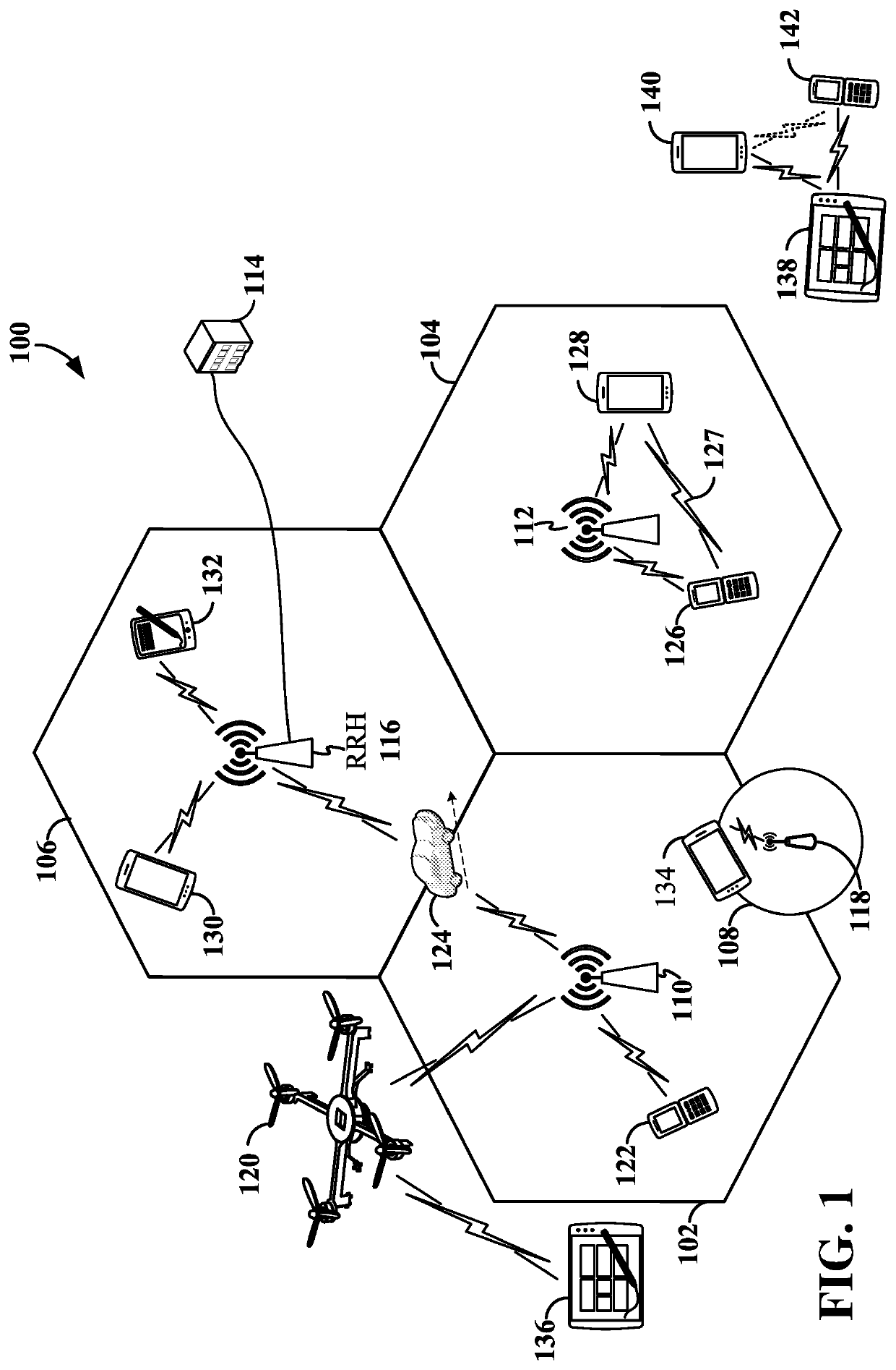
[0041]The various concepts presented throughout this disclosure may be implemented across a broad variety of telecommunication systems, network architectures, and communication standards. Referring now to FIG. 1, as an illustrative example without limitation, a simplified schematic illustration of an access network 100 is provided. The access network 100 m...


PUM


Abstract

Aspects of the present disclosure provide for the transmission of various synchronization signals with variable periodicity. For synchronization signals with long periodicity, in some aspects of the disclosure, the synchronization signals may be transmitted as single-frequency-network (SFN) synchronization signals and / or the synchronization signals may be repeated a number (N) of times within a synchronization burst to reduce user equipment (UE) search latency and improve UE measurement accuracy. In some examples, the synchronization signals may be repeated within a synchronization burst using a repetition pattern that may be configurable based on the periodicity of transmission or fixed for one or more periodicities of transmission.

Description

PRIORITY CLAIM[0001]This application claims priority to and the benefit of Provisional Patent Application No. 62 / 409,301 filed in the U.S. Patent and Trademark Office on Oct. 17, 2016, the entire content of which is incorporated herein by reference as if fully set forth below in its entirety and for all applicable purposes.TECHNICAL FIELD[0002]The technology discussed below relates generally to wireless communication systems, and more particularly, to synchronization in next generation (5G) wireless networks. Embodiments can provide and enable techniques for transmitting synchronization signals with variable periodicity and scrambling physical channels utilizing a zone identifier provided in a synchronization signal.INTRODUCTION[0003]Mobility management within a wireless communication network is typically implemented using a downlink-based mobility framework in which downlink reference signals are utilized by a user equipment (UE) to select a serving cell to which the UE connects. F...

Claims


Application Information

Patent Timeline
Patent Type & Authority Patents(United States)
IPC IPC(8): H04J11/00H04L5/00H04L5/14H04L27/00H04L27/26H04W56/00H04W88/10H04B1/69H04W88/02H04W88/08
CPCH04J11/0073H04J11/00H04J11/0069H04L5/00H04L5/0048H04L5/14H04L27/00H04L27/2613H04W56/0085H04W88/10H04B2001/6912H04J11/0076H04J2011/0003H04W56/00H04W56/001H04W88/02H04W88/08H04L27/26132
Inventor LY, HUNGLEE, HEECHOONJI, TINGFANG
Owner QUALCOMM INC
Why Eureka
Try Eureka