Orbital wrapping machine
- Summary
- Abstract
- Description
- Claims
- Application Information
AI Technical Summary
Benefits of technology
Problems solved by technology
Method used
Image
Examples
Embodiment Construction
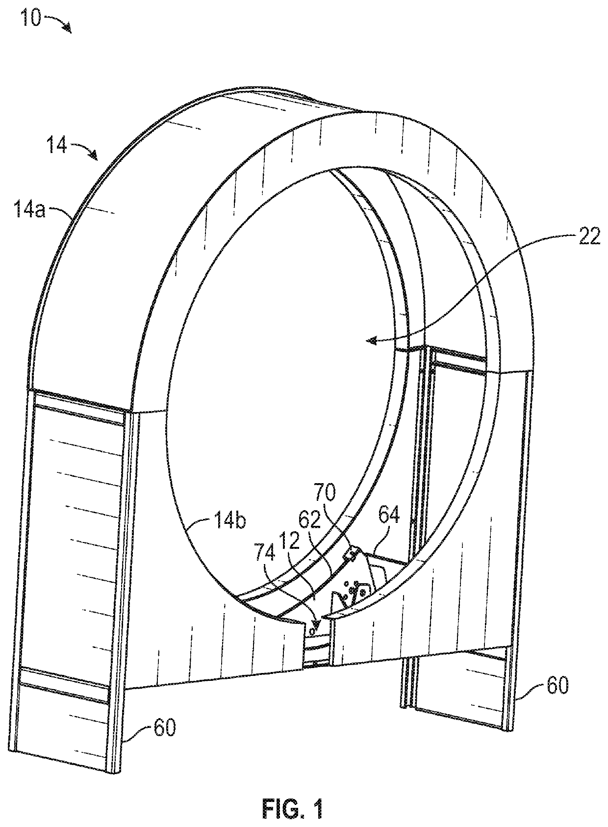
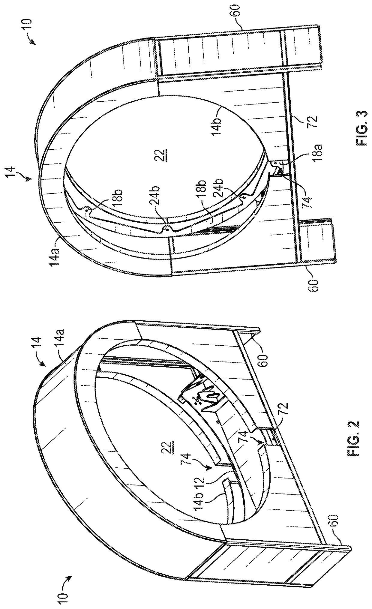
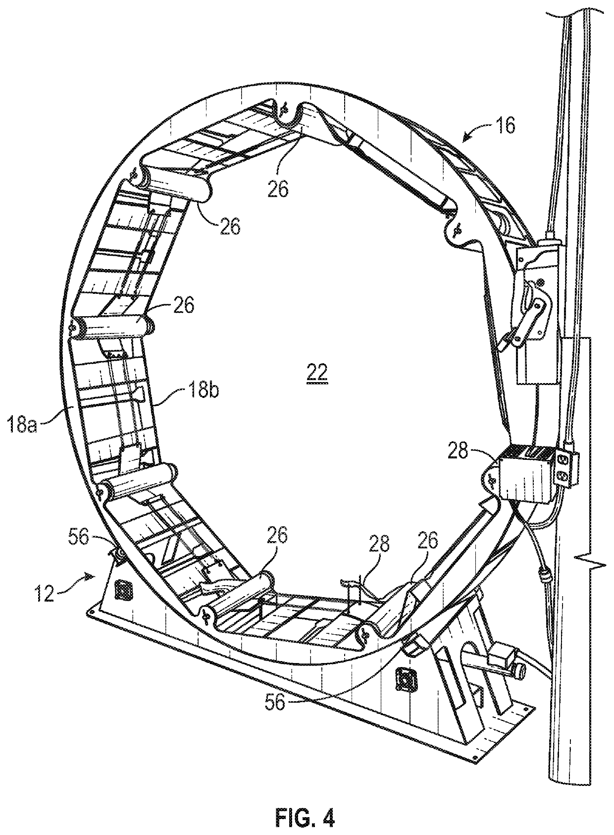
[0027]Referring now to the drawings and the illustrative embodiment depicted therein, an orbital wrapping machine 10 includes a support base 12 mounted in a wheel housing 14, such as shown in FIGS. 1-3. It should be appreciated that, to provide clearer views of the various structures, different portions of the orbital wrapping machine 10 are omitted from each drawing. A wrapping wheel 16 is rotatably supported on support base 12 in the wheel housing 14, and includes a pair of generally circular loops 18a, 18b that are spaced apart from one another and aligned substantially coaxially such as shown in FIGS. 4 and 5. The circular loops 18a, 18b are coupled together by a plurality of inner wheel brackets 20a and a plurality of outer wheel brackets 20b, such as shown in FIGS. 3-10. Wrapping wheel 16 defines an interior wrapping chamber 22 that, in the illustrated embodiment, is sufficiently large to receive a standard shipping / storage pallet (not shown) and the products supported thereon...
PUM
| Property | Measurement | Unit |
|---|---|---|
| Length | aaaaa | aaaaa |
| Force | aaaaa | aaaaa |
| Pressure | aaaaa | aaaaa |
Abstract
Description
Claims
Application Information
 - R&D
- Intellectual Property
- Life Sciences
- Materials
- Tech Scout
- Unparalleled Data Quality
- Higher Quality Content
- 60% Fewer Hallucinations
Browse by: Latest US Patents, China's latest patents, Technical Efficacy Thesaurus, Application Domain, Technology Topic, Popular Technical Reports.
© 2025 PatSnap. All rights reserved.Legal|Privacy policy|Modern Slavery Act Transparency Statement|Sitemap|About US| Contact US: help@patsnap.com


