Absolute position-measuring device

Active Publication Date: 2015-03-26
DR JOHANNES HEIDENHAIN GMBH
View PDF2 Cites 0 Cited by
  • Summary
  • Abstract
  • Description
  • Claims
  • Application Information

AI Technical Summary

Benefits of technology

[0011]Example embodiments of the present invention provide a absolute position-measuring device that is easy to service, and

Problems solved by technology

In contrast to absolute position-measuring devices, incremental position-measuring devices have a simple, robust design, but the drawback that no positional information is available directly following the switch-on operation, and it is necessary to first cross a reference mark in a so-called reference run before the absolute position can be inferred.
A technical field in which the use of absolute position-measuring devices continues to be problematic concerns systems or machines that are exposed to ionizing high-energy radiation, or whose application field requires the use of such radiation.
On the other hand, absolute position-measuring devices, which require a more complex design to determine an absolute positional value, tend to fail when exposed to ionizing, high-energy radiation.
Memory components are especially problematic, since memory content may change under the influence of radiation.
The failures caused by this problem are frequently difficult to understand because of the inconsistent error images they create.
In practice, the subassembly to be exchanged will frequently involve the first subassembly, not only because it is operated in the environment of ionizing hi

Method used


Image

  • Absolute position-measuring device
  • Absolute position-measuring device
  • Absolute position-measuring device

Examples


Example

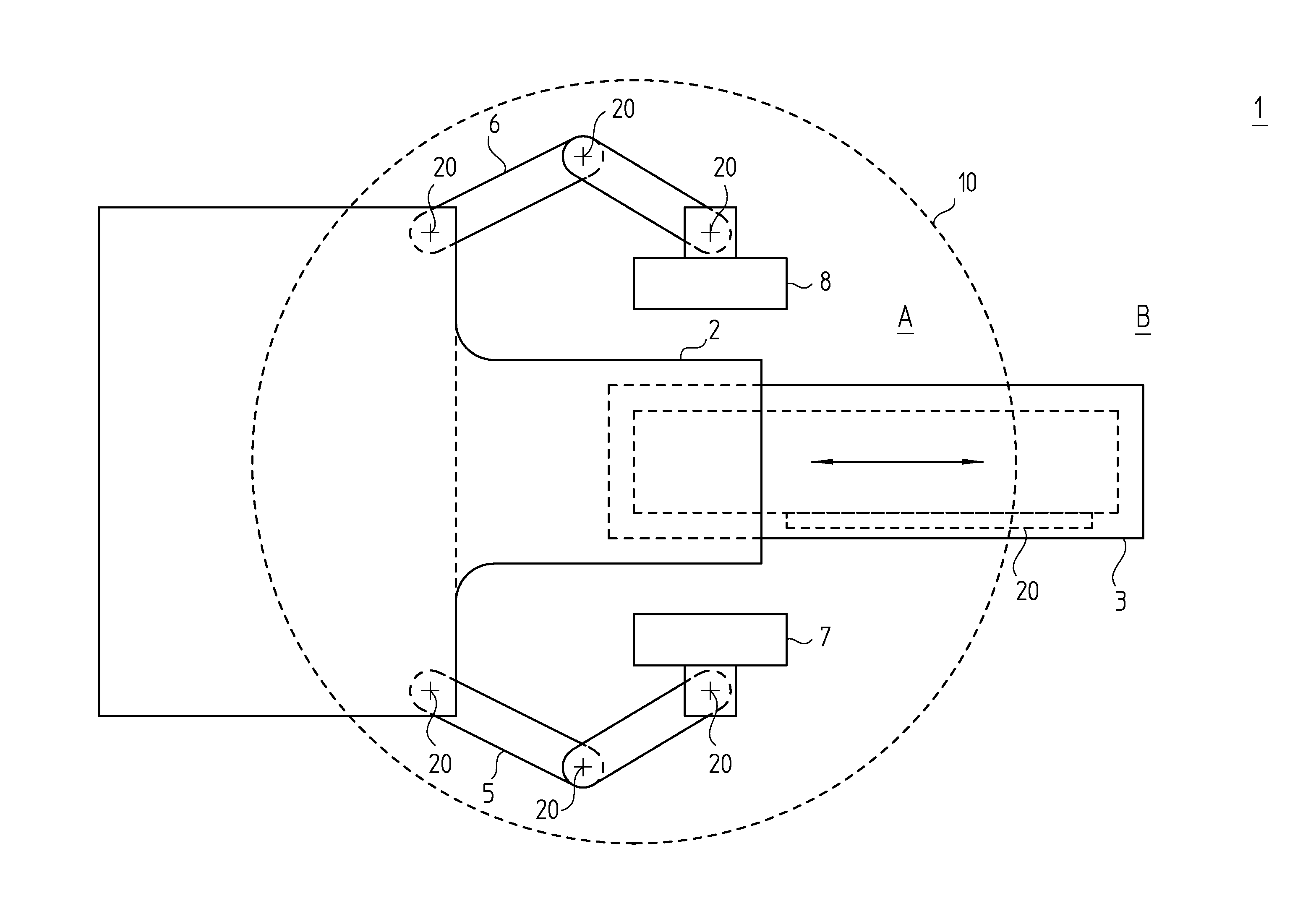
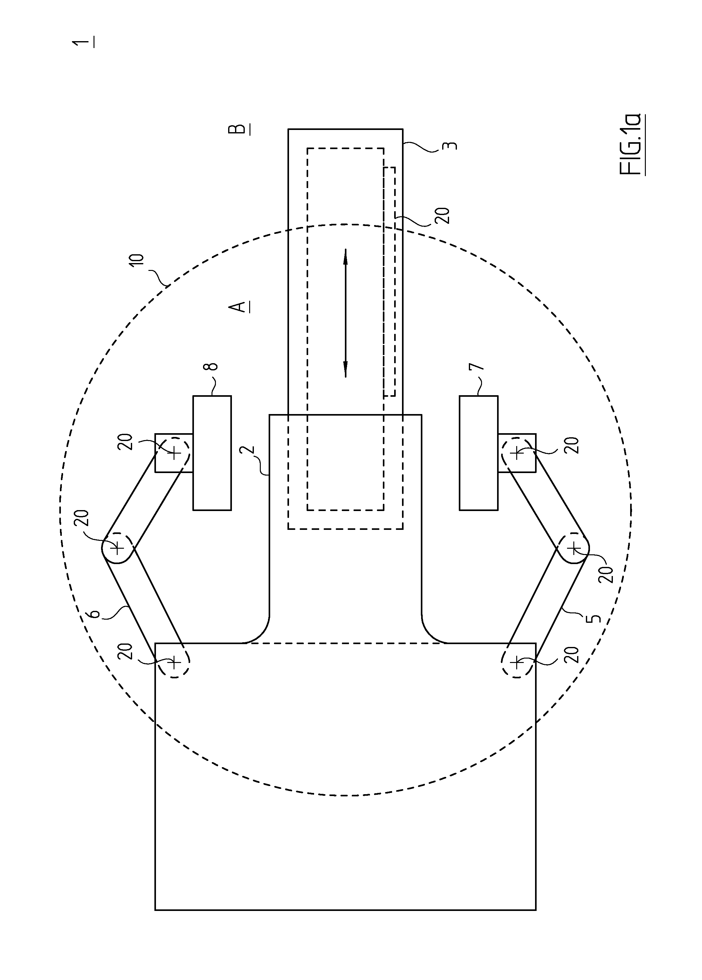
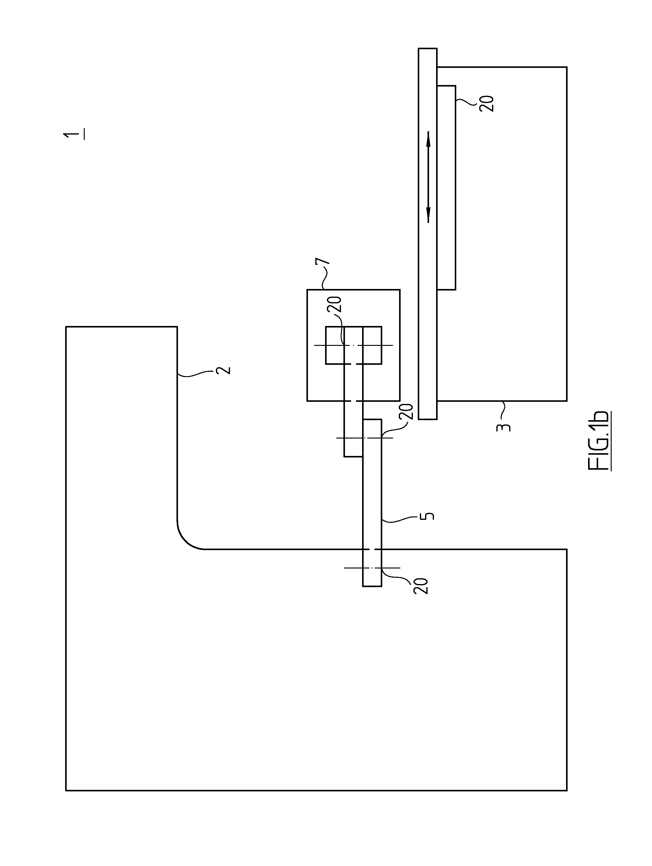
[0021]FIG. 1a is a schematic plan view and FIG. 1b is a schematic side view of a medical radiation device 1 as examples of a system in which ionizing high-energy radiation is used, especially gamma radiation, x-ray radiation or electron radiation. A radiation source 2 of radiation device 1 is arranged above the illustrated head end of a patient examination table 3. For clarity, a detailed depiction of the radiation source is omitted. It should be understood that the ionizing, high-energy radiation used for the radiation treatment of a tumor, for example, may occur predominantly within circle 10 illustrated in FIG. 1a. The area within circle 10 is therefore referred to below as radiation region A. Outside radiation region A, and thus outside circle 10, there is a radiation-proof region B.

[0022]The foregoing subdivision is greatly simplified and is mainly used for illustrative purposes. In practice, the energy of the occurring radiation decreases with rising distance from the radiatio...


PUM


Abstract

A position-measuring device includes: a first subassembly having a measuring standard on which at least one coded track is provided, and a scanning unit, which is able to generate position signals that may be used to generate an absolute digital position value by scanning the at least one coded track in a measuring direction; a second subassembly having at least one peripheral unit adapted to execute a supplementary or an auxiliary functionality of the position-measuring device; and a plurality of electrical lines, which connect the first subassembly and the second subassembly to each other for the transmission of electrical signals. The position-measuring device is able to be operated in an initialization mode and in a standard operating mode. All components of the first subassembly required for the operation in the standard operating mode are components that are suitable for use in a radiation region of a machine. Furthermore, an initialization memory is provided in the first subassembly, which includes the data required for the operation in the standard operating mode and which is not suitable for use in a radiation region of a machine. In the initialization mode, the content of the initialization memory is transmittable to a memory unit situated outside the radiation region. Only the content of the memory unit is used for the operation in the standard operating mode.

Description

CROSS-REFERENCE TO RELATED APPLICATIONS[0001]The present application claims priority to Application No. 10 2013 219 099.9, filed in the Federal Republic of Germany on Sep. 24, 2013, which is expressly incorporated herein in its entirety by reference thereto.FIELD OF THE INVENTION[0002]The present invention relates to an absolute position-measuring device, and to a method for operating a position-measuring device. Absolute position-measuring devices, as described herein, are suitable for use in systems or machines in which it is exposed to high-energy ionizing radiation.BACKGROUND INFORMATION[0003]Position-measuring devices are required in a wide variety of technical fields in order to determine the position (length and / or angle) of movable components in systems and machines. Based on their functional principle, position-measuring devices of this type are subdivided into two groups. There are, for example, incremental position-measuring devices, in which the position is determined by...

Claims


Application Information

Patent Timeline
IPC IPC(8): G01D9/00G01D5/00
CPCG01D5/00G01D9/00G01D3/08
Inventor THIELICKE, ERNSTAUER, DANIELBRATZDRUM, ERWIN
Owner DR JOHANNES HEIDENHAIN GMBH
Why Eureka
Try Eureka