3D printing using rotational components and improved light sources

a technology of rotational components and light sources, applied in the field of three-dimensional (3d) object formation methods, procedures and devices, can solve the problems of limiting the functional size of the object, long construction time, and the above process, and achieves high and accurate levels of detail, short time

Active Publication Date: 2021-10-12
ORANGE MAKER
View PDF9 Cites 0 Cited by
  • Summary
  • Abstract
  • Description
  • Claims
  • Application Information

AI Technical Summary

Benefits of technology

[0013]Described herein are methods, devices and systems for efficient 3D printing that address inefficiencies and deficiencies of currently existing 3D printing systems utilizing a single device. For ease of explanation and to provide an efficient nomenclature, the formation of 3D structures using the new techniques, procedures and devices set forth and incorporating features of the present invention are referred to as heliolithography. Heliolithography provides solutions to the above mentioned inherent problems associated with traditional prototyping techniques. It allows 3-dimensional solid physical products to be made directly from computer-driven data and reproduced with very high and accurate levels of detail, in a short time using a completely automated process. Certain aspects of Heliolithography are similar to stereolithography. Both Heliolithography-based and stereolithography-based processes can utilize a variety of materials as their base material, and these materials are solidified into physical parts through various solidification techniques, such as a free radical polymerization of photopolymers upon exposure to a precisely directed and focused actinic photon source of sufficient energy density. However, there are several key differences between heliolithography and stereolithography-based printing processes.
[0015]Methods and systems incorporating features of the present invention seek to solve the issue of having both simultaneously high construction resolutions while still preserving the ability to print large structural objects in a faster more economical way than can be achieved by the prior art. Such systems can utilize a continuous method for depositing and solidifying materials, for example, photocurable materials, in a rotational manner that results in a spiral build-up of material.
[0018]In some embodiments, Vertical-cavity surface-emitting lasers (VCSELs) are utilized as highly efficient light sources. These VCSELs can be incorporated into a material dispensing component, such as a print head, and can be configured with rotational components to allow for rotation of the VCSEL arrays to customize curing. In some embodiments, thermoelectric coolers (TAC) and / or fluid-based coolers can be utilized with the VCSELs to provide cooling.

Problems solved by technology

There are several limitations to the above processes.
This has the consequence of increasing the total amount of lines to be traced in a given area, resulting in longer construction times. Additionally, the process of submerging a platform in a vat of material is both limiting to the functional size of the object that can be created and also requires exposure of large volumes of photocurable materials to construct the 3D object.
Furthermore, the above method of subjecting a fluid surface to radiation poses its own set of issues with regards to consistent layer heights and errors that can be caused from disturbances to the liquid surface.
These disturbances can result from both internal and external sources of vibration.
This limits the vertical resolution that is attainable with a given range of materials.
These processes for removal of the adhesion force place the vat, the build platform, the raising element for the build platform and the newly solidified geometries of the printed object under high stress loads that can decrease the functional life of the machine and its components, as well as causing deformations and delamination of the object being constructed.
This method, however, doubles the construction time and increases the chance for product failure due to delamination caused by increasing the amount of unsupported areas to be solidified.
Additionally, conventional light sources utilized in 3D printers have there own limitations and improved light sources allowing for faster cure times is also desirable.
However, there are several key differences between heliolithography and stereolithography-based printing processes.

Method used


Image

  • 3D printing using rotational components and improved light sources
  • 3D printing using rotational components and improved light sources
  • 3D printing using rotational components and improved light sources

Examples


Embodiment Construction

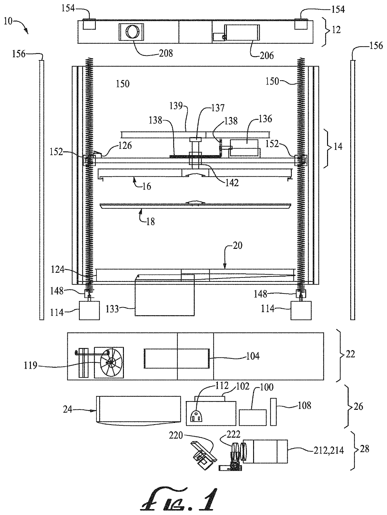
[0056]The present disclosure sets forth methods and devices for efficient 3D printing that address conventional inefficiencies and deficiencies while utilizing a single compact device. As illustrative of such methods and 3D production devices, the dispensing of a photocurable substance onto transparent substrate, the selective curing and solidified of such materials and the retrieval of the solidified product is described. However, one skilled in the art, based on the teachings herein, will recognize that the apparatus and techniques described herein are not limited to the use of photopolymers along with the irradiation sources suitable to effect solidification, but can be readily adaptable to a broad range of flowable materials that can be rapidly solidified for the continuous formation of solid, three dimensional objects.

[0057]Throughout this disclosure, the preferred embodiments herein and examples illustrated are provided as exemplars, rather than as limitations on the scope of ...


PUM

PropertyMeasurementUnit
thicknessaaaaaaaaaa
thicknessaaaaaaaaaa
sizeaaaaaaaaaa

Abstract

Methods, devices and systems for efficient 3D printing that address conventional inefficiencies while utilizing a single compact device are set forth. Some embodiments utilize a circular-shaped build area revolving symmetrically around a single center point utilizing a continuous helical printing process. In some embodiments, vertical-cavity surface-emitting lasers (VCSELs) are utilized as an energy source for curing the print material. The VCSELs can be integrated with the print head and can form an array which can be staggered or linear. In some embodiments, the VCSELs (and the corresponding print head)can be connected to a rotating platform, which can rotate independently from the revolving build area. In some embodiments, a thermoelectric cooler and / or a fluid cooler can provide cooling to the VCSELS.

Description

CROSS REFERENCE TO RELATED APPLICATIONS[0001]This application claims priority from U.S. Provisional Application Ser. No. 62 / 448,905. This application is also a continuation-in-part of U.S. Ser. No. 15 / 088,365, filed Apr. 1, 2016, which is a divisional of U.S. patent application Ser. No. 14 / 207,353, filed Mar. 12, 2014, now U.S. Pat. No. 9,321,215, which claims the benefit of U.S. Provisional Application Ser. No. 61 / 778,285, filed on Mar. 12, 2013. Each of these applications are hereby incorporated herein in their entirety by reference.BACKGROUND OF THE INVENTIONField of the Invention[0002]Described herein are methods, procedures and devices for forming three-dimensional (3D) objects from a wide variety of media, such as a polymeric, biological or metallic materials. The methods, procedures and devices are programmed to produce desired three dimensional (3D) structures using polymerization, crosslinking, curing, sintering, melting or solidification and similar techniques in a manner ...

Claims


Application Information

Patent Timeline
Patent Type & Authority Patents(United States)
IPC IPC(8): B29C64/112B33Y10/00B33Y30/00B29C64/40B29C64/268B29C64/20
CPCB29C64/112B29C64/20B29C64/268B29C64/40B33Y10/00B33Y30/00B29K2909/08
Inventor DUDLEY, KURTTERSIGNI, JAMES
Owner ORANGE MAKER
Why Eureka
Try Eureka