Control system for hybrid vehicle

a control system and hybrid technology, applied in the direction of propulsion parts, external condition input parameters, transportation and packaging, etc., can solve the problems of motor generator and battery not being protected properly, overcharging of batteries, overheating of motor generators, etc., to reduce engine speed and torque, reduce engine torque and power, and reduce engine intake.

Active Publication Date: 2021-10-12
TOYOTA JIDOSHA KK
View PDF9 Cites 1 Cited by
  • Summary
  • Abstract
  • Description
  • Claims
  • Application Information

AI Technical Summary

Benefits of technology

[0009]In a non-limiting embodiment, the high-power mode may include: a first control mode in which the hybrid vehicle is decelerated while reducing the torque and the speed of the engine such that an operating point of the engine is shifted along an optimum fuel economy curve; and a second control mode in which the hybrid vehicle is decelerated while reducing the torque of the engine at a same rate as in the first control mode, reducing the speed of the engine at a faster rate than in the first control mode, and reducing the power of the engine at a slower rate than in the low-power mode, so as to reduce emission.
[0017]Thus, according to the exemplary embodiment of the present disclosure, the hybrid vehicle is decelerated by controlling the speed of the engine by the first motor, and by applying the brake torque generated by the second motor to the drive wheels. When decelerating the hybrid vehicle in the high-power mode, the torque and the power of the engine are reduced at the rate slower than the predetermined rate of the low-power mode. In this situation, therefore, the air intake to the engine is reduced slower than in the low-power mode in which the speed and the torque of the engine are reduced promptly. For this reason, the air intake can be estimated accurately to control an air / fuel ratio to reduce emission of the polluting gas.
[0018]As described, the high-power mode may be selected from the first control mode and the second control mode. In the first control mode, specifically, the engine is controlled in such a manner that an operating point of the engine is shifted along an optimum fuel economy curve. On the other hand, in the second control mode, the torque of the engine is reduced at a substantially same rate as in the first control mode, the speed of the engine is reduced at a faster rate than in the first control mode, and the power of the engine is reduced at a slower rate than in the low-power mode. In the second control mode, therefore, the output power of the engine may be reduced while reducing a regeneration amount of the second motor compared to the first control mode. That is, for example, if the state of charge level of the electric storage device is high, the hybrid vehicle is allowed to be decelerated while reducing the emission and charging the electric storage device within an upper limit by selecting the second control mode. For this reason, an overcharging of the electric storage device can be prevented.
[0019]The control mode of the engine may be selected based on the fact that the second motor is in a condition possible to generate the brake torque for decelerating the vehicle while maintaining the output torque of the engine. For example, in order to decelerate the hybrid vehicle while reducing the output power of the engine slowly to reduce emission, the second motor is allowed to generate the brake torque greater than the output torque of the engine to decelerate the hybrid vehicle if a temperature of the second motor itself or a power control unit falls within a predetermined range. Therefore, the first control mode or the second control mode is selected when e.g., the temperature of the second motor is lower than the predetermined value. For this reason, the control mode of the engine can be selected properly to reduce emission of the polluting gas while protecting the electric storage device, the motors, and the power control unit.
[0020]In addition, the control mode of the engine may be selected based on the required deceleration taking account of the shift range, the operating amount of a brake pedal, the operating speed of a predetermined pedal in a one-pedal mode, or the road grade. For this reason, the required deceleration can be achieved while reducing emission of the polluting gas and protecting the electric storage device and the motors.

Problems solved by technology

In addition, given that such control is applied to a hybrid vehicle having an engine and a motor-generator, the motor-generator and a battery may not be protected properly depending on a condition of the engine.
For example, an overheating of the motor-generator and an overcharging of the battery would be caused.

Method used


Image

  • Control system for hybrid vehicle
  • Control system for hybrid vehicle
  • Control system for hybrid vehicle

Examples


Embodiment Construction

)

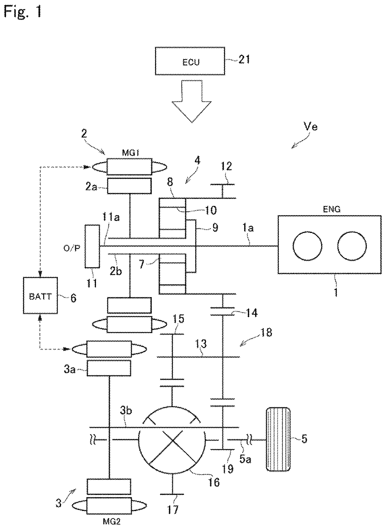
[0038]Preferred embodiments of the present disclosure will now be explained with reference to the accompanying drawings. Referring now to FIG. 1, there is shown one example of a powertrain of a hybrid vehicle (as will be simply called the “vehicle” hereinafter) Ve to which the control system according to the exemplary embodiment of the present disclosure is applied. A prime mover of the vehicle Ve comprises an engine (referred to as ENG in FIG. 1) 1, a first motor (referred to as MG1 in FIG. 1) 2, and a second motor (referred to as MG2 in FIG. 1) 3. In the vehicle Ve, an output power of the engine 1 is distributed to the first motor 2 and drive wheels 5 through a power split mechanism 4. An electric power generated by the first motor 2 may be supplied to the second motor 3 to generate torque, and a drive force generated by the second motor 3 may be delivered to the drive wheels 5.

[0039]Each of the first motor 2 and the second motor 3 is a motor-generator that is operated not only a...


PUM


Abstract

A control system for a hybrid vehicle configured to reduce an exhaust gas during deceleration of the vehicle, and to protect a motor and a battery. A control mode of the engine may be selected from: a low-power mode in which the hybrid vehicle is decelerated by reducing a torque and a power of the engine at a predetermined rate while generating the brake torque by the motor; and a high-power mode in which the hybrid vehicle is decelerated by reducing the torque and the power of the engine at a rate slower than the predetermined rate of the low-power mode while generating the brake torque by the motor.

Description

CROSS REFERENCE TO RELATED APPLICATIONS[0001]The present application claims the benefit of priority to Japanese Patent Application No. 2018-149333 filed on Aug. 8, 2018 with the Japanese Patent Office.BACKGROUNDField of the Disclosure[0002]Embodiments of the present disclosure relate to the art of a control system for a hybrid vehicle in which a prime mover includes an engine and a motor-generator, and especially to a control system configured to control the engine during deceleration of the hybrid vehicle.Discussion of the Related Art[0003]JP-A-2017-223309 describes a control apparatus for a vehicle configured to prevent an abrupt raise in an engine speed during deceleration of the vehicle, and to reduce a shock that occurs due to loss of backlash in a power transmission path of the vehicle. Specifically, the control apparatus taught by JP-A-2017-223309 is applied to a vehicle comprising a lock-up clutch. According to the teachings of JP-A-2017-223309, the control apparatus selects...

Claims


Application Information

Patent Timeline
Patent Type & Authority Patents(United States)
IPC IPC(8): B60W30/18B60W30/188B60W20/14
CPCB60W30/18127B60W20/14B60W30/188B60W10/06B60W10/08B60W2510/0638B60W2510/244B60W2510/246B60W2540/10B60W2540/12B60W2710/0666B60W2710/083B60K6/445B60W30/182B60W20/13B60W2540/215B60W2540/106B60W2552/15B60W2050/0026B60W20/00B60W50/082B60W2710/0672Y02T10/84Y02T10/92
Inventor TSUDA, SATOSHI
Owner TOYOTA JIDOSHA KK
Why Eureka
Try Eureka