
Decoy stand with rotating arm

a technology of decoys and arms, applied in the field of waterfowl decoys, can solve the problems of increased chances of waterfowl luring into the hunter's spread, increased cost of products and weight, and more difficult to carry ou

Active Publication Date: 2021-10-19
REYNOSO TYLER JAMES +1
View PDF39 Cites 4 Cited by
  • Summary
  • Abstract
  • Description
  • Claims
  • Application Information

AI Technical Summary

Benefits of technology

The invention is an actuator that can move a crossbeam back and forth. It is powered by a string and a spring, which allows the crossbeam to lower one end while raising the other end. The actuator can be pulled or released to cause the crossbeam to move in a teetering motion. This technology can be used to create a realistic training experience for firefighters and other emergency responders.

Problems solved by technology

Such improved movement in a decoy spread ultimately advances the decoy spread and thereby increases the chances of luring waterfowl into the hunters spread.
Although this system may effectively simulate waterfowl hovering above the water, it necessarily requires a battery pack and motor within the apparatus itself to create horizontal spinning.
With the required battery and motor there also comes an added cost for the product and weight that makes it more challenging to carry out to the spread and takes more time to set up.
Conversely, the hunter may elect to setup the Vortex system near a non-battery power source but in doing so limits potential hunting locations.
However, this system only provides a single decoy on a single arm and does not provide visual ques on both sides of the actuator facilitating movement of the decoy.
The range of motion of this system is also limited where the base is position on the ground, such as a river bank, and the arm extends over the water.
Most waterfowl hunting involves hunting over water with little to no land available in most circumstances which limits where you can use systems that require land for supporting the base of the decoy system.

Method used


Image

  • Decoy stand with rotating arm
  • Decoy stand with rotating arm

Examples


Embodiment Construction

[0019]The following description of the preferred embodiment(s) is merely exemplary in nature and is in no way intended to limit the invention, its application, or uses.

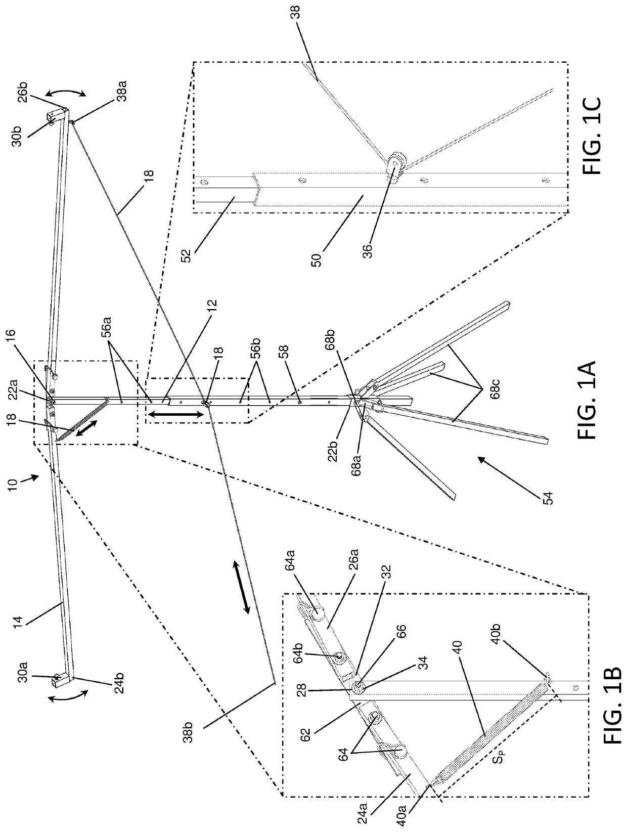
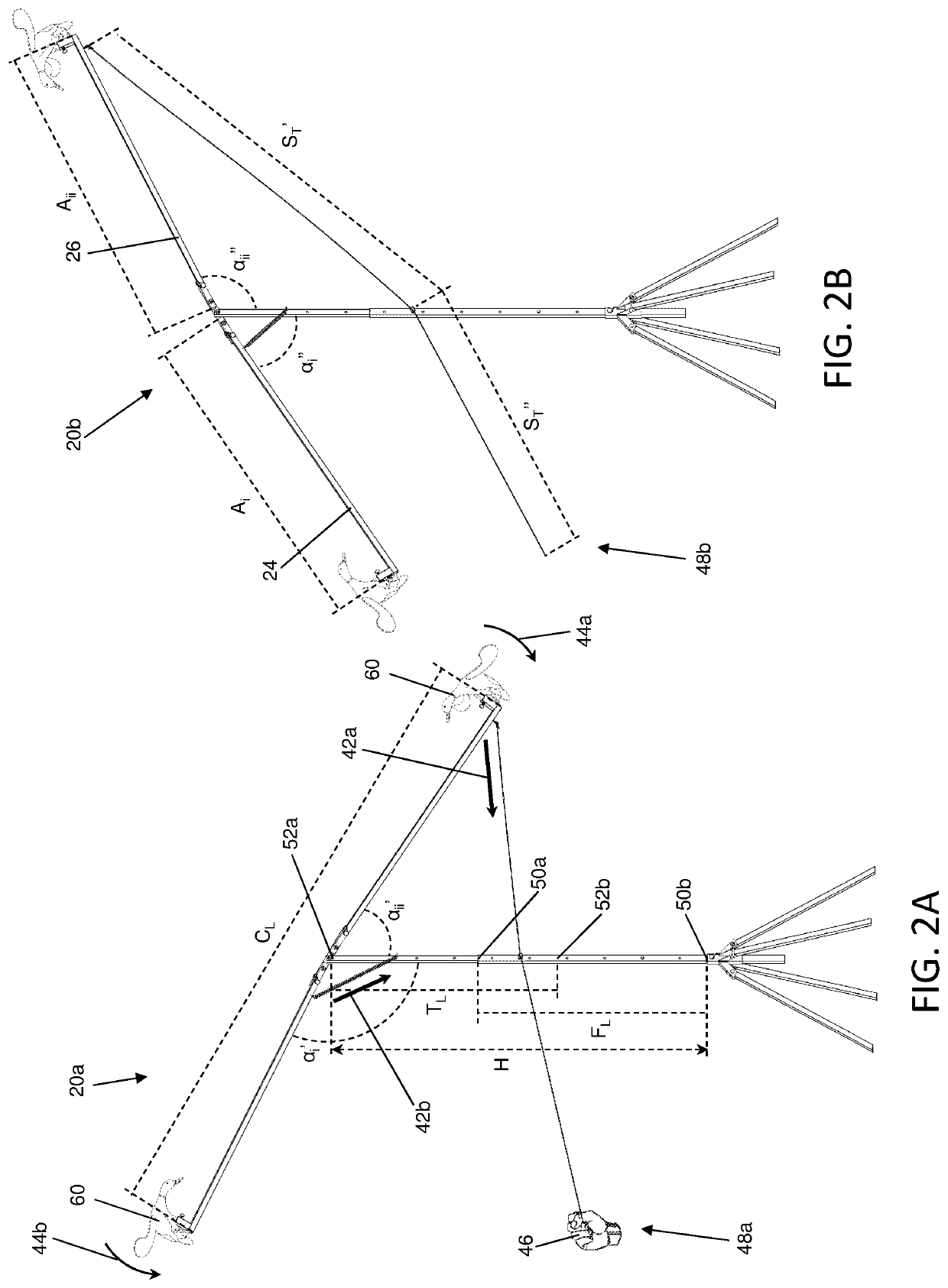
[0020]The decoy system 10 with rotating arm consists of a crossbeam 14 connected to a support beam 12 by a hinge 16 with an actuator 18 moving the crossbeam in a seesaw motion within a plane. The seesaw motion of the crossbeam causes one end of the crossbeam to raise in the air above the hinge while the opposite end simultaneously dips towards the water level below the hinge. Accordingly, the crossbeam is connected to the top end of the support beam at the midpoint of the crossbeam by the hinge. Further, mounting brackets 30 are positioned on opposite ends of the crossbeam which hold decoys 60 that simulate waterfowl landing and taking off from water as the crossbeam seesaws back and forth.

[0021]As particularly described herein, the support beam includes a top end 22a connected to the support beam mounting portion of ...


PUM


Abstract

The present invention is a decoy system that simulates waterfowl taking off and landing byway of a string, pulley and spring which collectively cause a crossbeam holding waterfowl decoys to raise and lower relative to the surface of the water in which the system sits. When the string is pulled one end of the crossbeam holding one decoy lowers and the opposite end of the beam holding either a counterweight or another decoy raises. When the string is released a spring attached to the opposite side of the beam from the string moves the beam towards its original position and thereby the string and spring actuate a teetering motion that provides a visual que on both sides of the hinge at the midpoint of the crossbeam.

Description

CROSS-REFERENCE TO RELATED APPLICATIONS[0001]This application claims priority from U.S. Provisional Patent Application No. 62 / 711,882 filed on Jul. 30, 2018.STATEMENT REGARDING FEDERALLY SPONSORED RESEARCH[0002]Not Applicable.APPENDIX[0003]Not Applicable.BACKGROUND OF THE INVENTIONField of the Invention[0004]The present invention relates to waterfowl decoys, and more particularly to actuated waterfowl decoys having vertical movement.Related Art[0005]Waterfowl decoys have long been used for luring waterfowl into hunters decoy spreads to increase the likelihood of a successful hunt. Generally waterfowl decoy systems share the goal of simulating live waterfowl in an attempt to aid hunters in attracting game. Known decoys include solid floating decoys that merely float atop water proximate to a hunters blind while other known decoys simulate moving waterfowl, for example ducks as they land or takeoff from a water surface, by providing spinning-wings that may either be powered or wind op...

Claims


Application Information

Patent Timeline
IPC IPC(8): A01M31/06
CPCA01M31/06
Inventor REYNOSO, TYLER JAMESSHILHARVEY, CODY CHRISTOPHER
Owner REYNOSO TYLER JAMES
Learn More