Encoding device, decoding device, and program
a decoding device and encoding technology, applied in the field of encoding devices, decoding devices, and programs, can solve the problems of reducing encoding efficiency and encoding efficiency, and achieve the effect of suppressing a reduction in encoding efficiency and reducing an increase in entropy
- Summary
- Abstract
- Description
- Claims
- Application Information
AI Technical Summary
Benefits of technology
Problems solved by technology
Method used
Image


Examples
first embodiment
[0051]Hereinafter, an encoding device 1 and a decoding device 3 according to a first embodiment of the present invention will be described with reference to FIGS. 1 to 5. Here, the encoding device 1 and the decoding device 3 according to the present embodiment are configured to correspond to intra prediction in a video encoding method such as HEVC. The encoding device 1 and the decoding device 3 according to the present embodiment are configured so as to correspond to arbitrary video encoding methods as long as they are of a video encoding method that performs intra prediction.
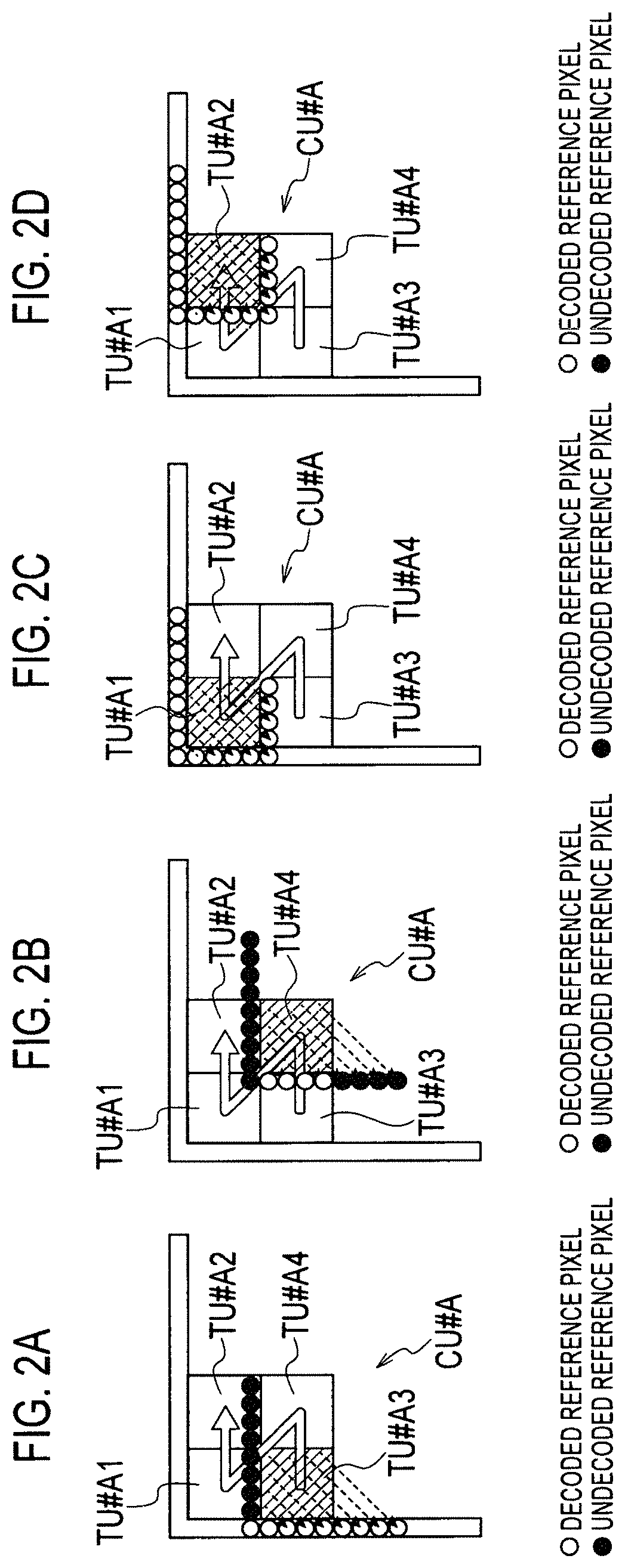
[0052]The encoding device 1 according to the present embodiment is configured to encode an original image of a frame unit constituting a video by dividing the original image into CUs. In addition, the encoding device 1 according to the present embodiment may be configured to be able to divide a CU into a plurality of TUs. Hereinafter, in the present embodiment, a case where the CU is divided into the plurality...
second embodiment
[0152]Hereinafter, referring to FIGS. 6 and 7, an encoding device 1 and a decoding device 3 according to a second embodiment of the present invention will be described, focusing on the difference from the encoding device 1 and the decoding device 3 according to the first embodiment.
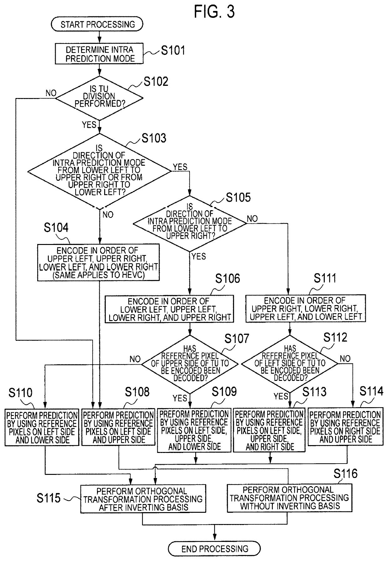
[0153]In the encoding device 1 according to the present embodiment, if an intra predictor 14a generates a predicted image by using reference pixels positioned on at least one of the right side and the lower side, an orthogonal transformer / quantizer 14c is configured to perform orthogonal transformation processing after inverting a residual signal generated by a residual signal generator 14b in at least one of a horizontal direction and a vertical direction.
[0154]For example, if the intra predictor 14a generates the predicted image by using reference pixels positioned on the left side and the lower side, the orthogonal transformer / quantizer 14c may be configured to perform orthogonal transformation process...
third embodiment
[0178]Hereinafter, the encoding device 1 and the decoding device 3 according to the first embodiment of the present invention will be described with reference to FIGS. 1, 2, 4, 8, and 9. Here, the encoding device 1 and the decoding device 3 according to the present embodiment are configured to correspond to intra prediction in a video encoding method such as HEVC. The encoding device 1 and the decoding device 3 according to the present embodiment are configured so as to correspond to arbitrary video encoding methods as long as they are of a video encoding method that performs intra prediction.
[0179]The encoding device 1 according to the present embodiment is configured to encode an original image of a frame unit constituting a video by dividing the original image into CUs. In addition, the encoding device 1 according to the present embodiment may be configured to be able to divide a CU into a plurality of TUs. Hereinafter, in the present embodiment, a case where the CU is divided in...
PUM
 Abstract
Description
Claims
Application Information
 - R&D
- Intellectual Property
- Life Sciences
- Materials
- Tech Scout
- Unparalleled Data Quality
- Higher Quality Content
- 60% Fewer Hallucinations
Browse by: Latest US Patents, China's latest patents, Technical Efficacy Thesaurus, Application Domain, Technology Topic, Popular Technical Reports.
© 2025 PatSnap. All rights reserved.Legal|Privacy policy|Modern Slavery Act Transparency Statement|Sitemap|About US| Contact US: help@patsnap.com