
Roller leveler with upper and lower leveling rollers and method for the simple and rapid inspection, maintenance, and servicing of the upper leveling rollers of a roller leveler

a technology of leveling rollers and leveling rollers, which is applied in the direction of metal-working equipment, manufacturing tools, shaping tools, etc., can solve the problems of dirt accumulation on the leveling machine and to corresponding wear, impair the leveling, and increase the amount of normal wear caused by dir

Active Publication Date: 2021-11-16
ARKU MASCHENBAU
View PDF25 Cites 0 Cited by
  • Summary
  • Abstract
  • Description
  • Claims
  • Application Information

AI Technical Summary

Benefits of technology

The invention relates to a leveling machine that uses a drive device to shift and level equipment. The leveling rollers are engaged with the drive device using positive profiles and, under pressure, are rotated to align with the coupling elements. The rollers press on the equipment to shift and align them, and once the rollers and equipment are aligned, the machine is ready to perform its leveling task. A light barrier can be used to confirm that all the rollers are properly connected. The technical effects of this invention are improved alignment accuracy and efficiency in the leveling process.

Problems solved by technology

In other cases, special processing techniques applied to pieces such as welding also generate impurities, which, during the following leveling process, can lead to the accumulation of dirt on the leveling machine and to corresponding wear, especially of the leveling rollers.
The dirt introduced into the leveler by the material to be leveled can adhere both to the leveling rollers themselves and to the back-up rollers and can thus impair the leveling result.
In addition, dirt also increases the amount of wear normally caused by the leveling work.
The servicing and cleaning of the back-up rollers requires a great deal of time in the prior art patents because the leveler must be partially disassembled and then reassembled.
This indicates, however, that a great deal of time is required, even when only light cleaning work is to be carried out, for example, which doesn't even call for the removal of the leveling rollers.
Another disadvantage of the prior art is that work of this type on the upper replaceable cassette must be carried out in an overhead manner.
That is, the worker must reach up from underneath to the replaceable cassette, which is suspended from the upper slider plate; this is an extremely cumbersome working position from an ergonomic point of view.
It is not possible, furthermore, to remove the entire upper replaceable cassette together with the leveling rollers and back-up roller blocks and to replace it quickly.

Method used


Image

  • Roller leveler with upper and lower leveling rollers and method for the simple and rapid inspection, maintenance, and servicing of the upper leveling rollers of a roller leveler
  • Roller leveler with upper and lower leveling rollers and method for the simple and rapid inspection, maintenance, and servicing of the upper leveling rollers of a roller leveler
  • Roller leveler with upper and lower leveling rollers and method for the simple and rapid inspection, maintenance, and servicing of the upper leveling rollers of a roller leveler

Examples


Embodiment Construction

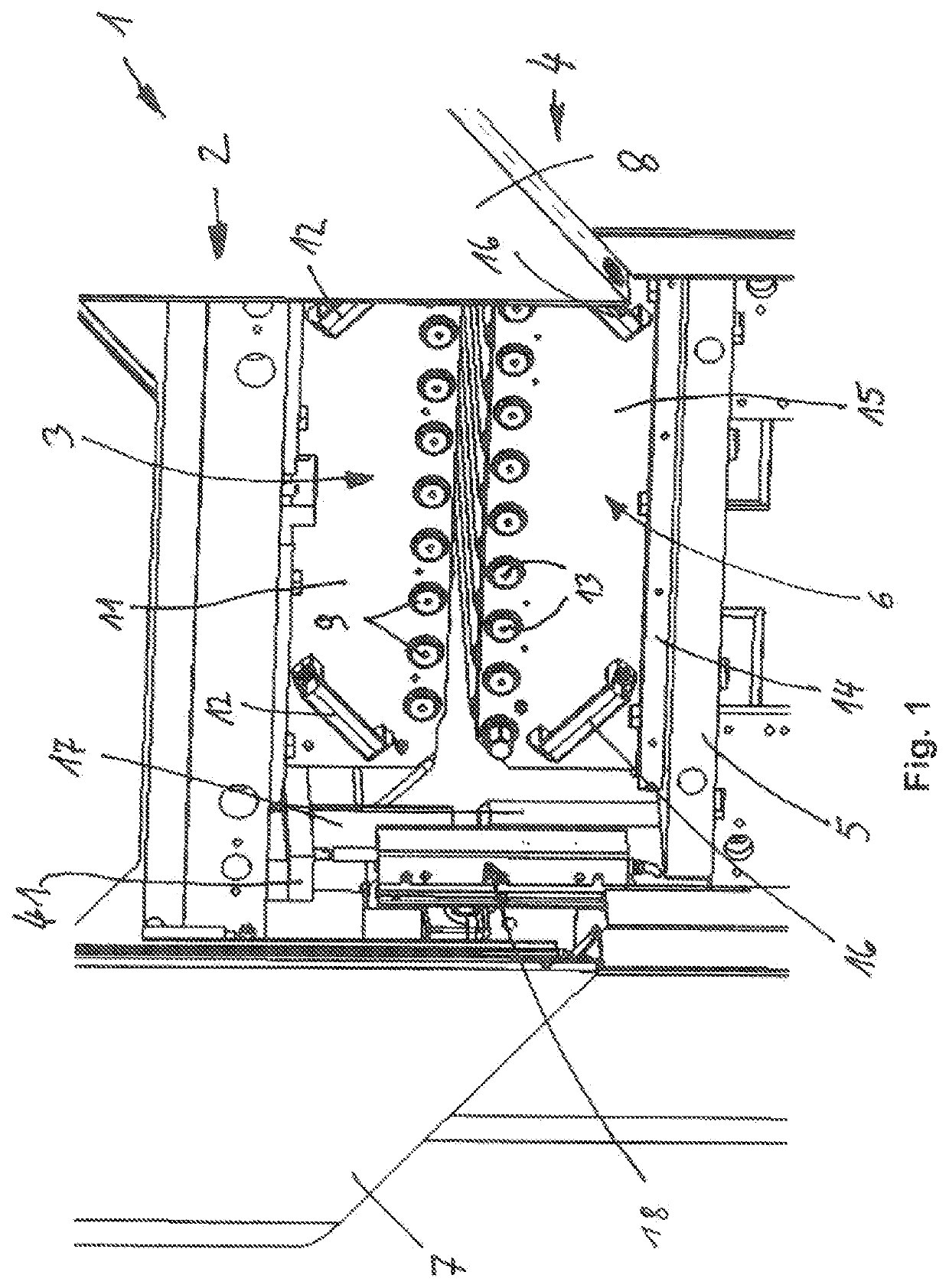
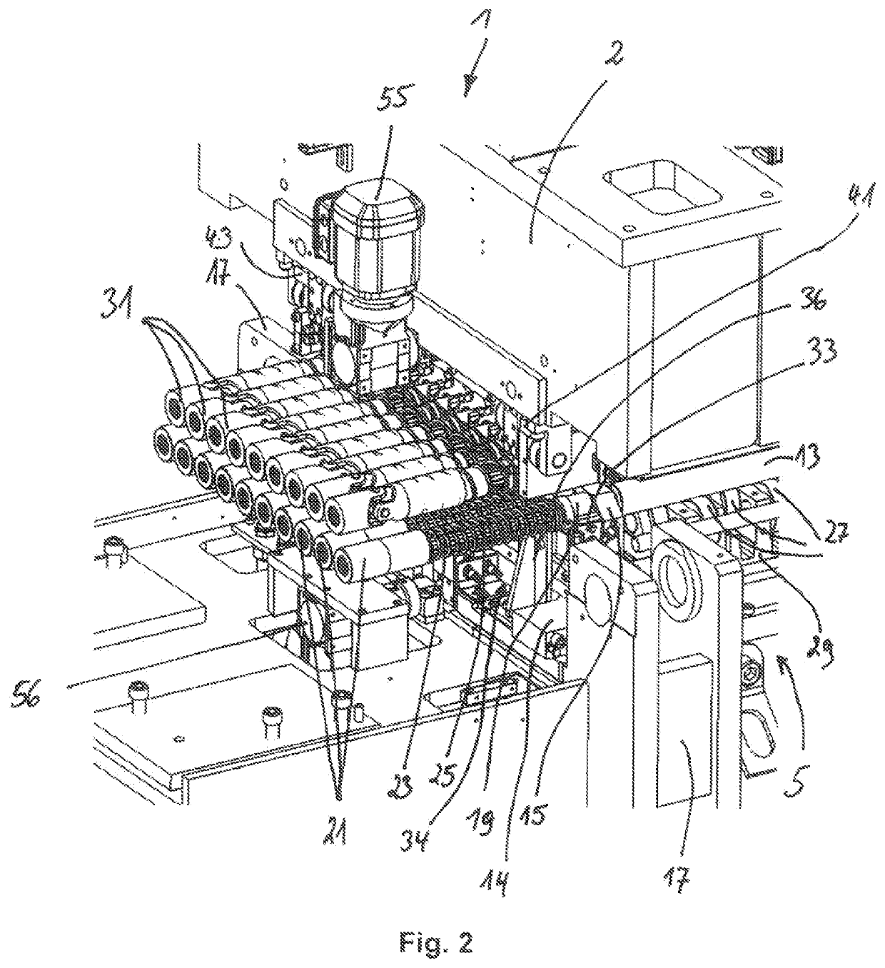
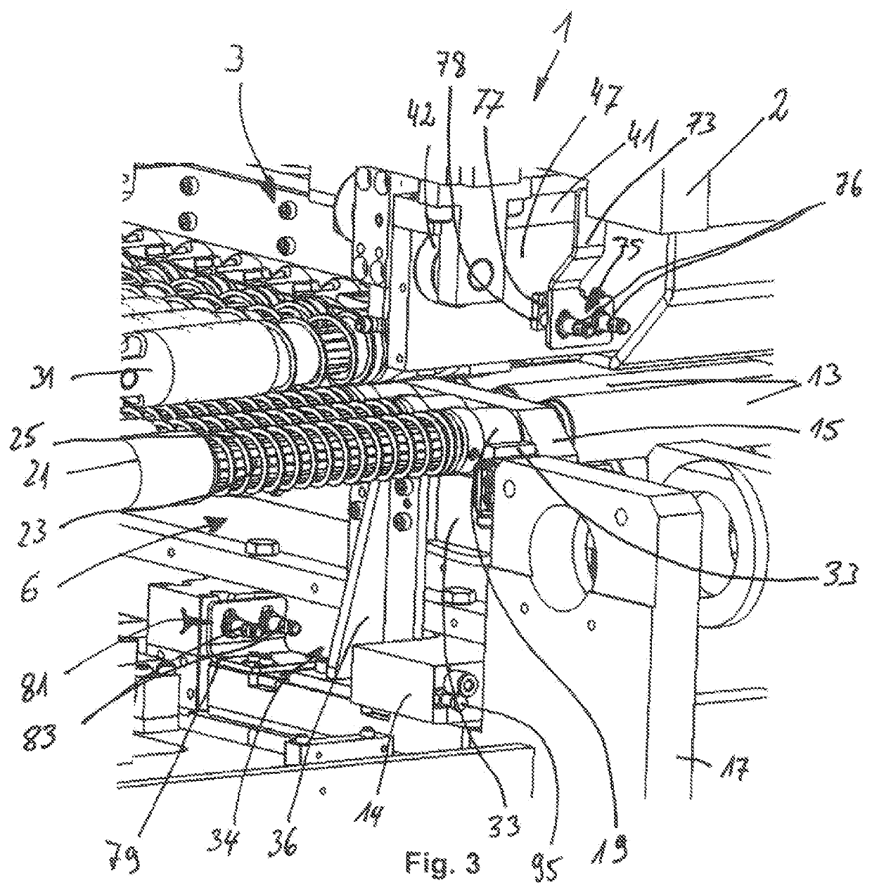
[0047]FIG. 1 shows a perspective view of a roller leveler 1 according to the invention which includes an upper roller frame 2 and a lower roller frame 4; the upper frame has an upper leveling unit 3. The lower roller frame 4 has a machine bed or base 5. A lower leveling unit 6 is arranged on the machine bed 5.

[0048]Roller leveler 1 includes a machine cover, with a left cover section 7 and a right cover section 8, both of which are shown in the open position and which give access to roller frames 2 and 4.

[0049]Roller leveler 1 has a hydraulic drive in each of the four corners of the roller leveler to move upper roller assembly 2 relative to lower the roller assembly 4. The hydraulic drive at the front left in FIG. 1 is shown in only a highly schematic manner, i.e., without the hydraulic cylinder but with its mounting frame 17. This drive is not described in any further detail.

[0050]Upper leveling unit 3 includes upper leveling rollers 9, which are supported in upper bearing plates 11...


PUM

PropertyMeasurementUnit
pressureaaaaaaaaaa
gravityaaaaaaaaaa
widthaaaaaaaaaa

Abstract

A roller leveler and related method for leveling stock which includes an upper roller frame with an upper leveling unit, and a lower roller frame which has a machine bed with a lower leveling unit. The upper roller frame can be moved upward and downward relative to the lower roller frame by hydraulic drives. The upper leveling unit includes a plurality of upper leveling rollers and the lower leveling unit has a plurality of lower leveling rollers. The upper leveling rollers are supported with upper bearing plates and the lower leveling rollers are supported with lower bearing plates. At least several of the upper and lower leveling rollers are connected at one end to drive shafts of a drive device. A frame is moveable into and out of the roller leveler.

Description

CROSS-REFERENCE TO RELATED APPLICATION[0001]The present application is a U.S. national phase entry of pending International Patent Application No. PCT / EP2017 / 057858, international filing date Apr. 3, 2017, which claims priority to European Patent Application No. EP16,170840.9, filed May 23, 2016, the contents of which are incorporated by reference in their entireties.FIELD OF THE INVENTION[0002]The present invention relates to a roller leveler for leveling material for stock to be leveled, especially strips and parts of metal, in which the upper leveling rollers can be quickly and easily inspected, maintained, and serviced as well as cleaned.[0003]The present invention also relates to a method for the simple and rapid inspection, maintenance, servicing, and cleaning of especially the upper leveling rollers of a roller leveler.BACKGROUND OF THE INVENTION[0004]After the production process, the surfaces of rolled materials such as strip steel or rolled plate, especially hot-rolled plat...

Claims


Application Information

Patent Timeline
Patent Type & Authority Patents(United States)
IPC IPC(8): B21D1/02B21D37/14
CPCB21D1/02B21D37/147
Inventor ARMBRUSTER, CHRISTIANHARTMANN, CHRISTIAN
Owner ARKU MASCHENBAU
Learn More