
Calibration apparatus and calibration method for coordinate system of robotic arm

a technology of robotic arm and calibration method, which is applied in the field of robotic arm, can solve the problems of inability to provide effective help to the above calibration apparatus, inconvenient control of the robotic arm,

Pending Publication Date: 2022-03-31
DELTA ELECTRONICS INC
View PDF10 Cites 0 Cited by
  • Summary
  • Abstract
  • Description
  • Claims
  • Application Information

AI Technical Summary

Benefits of technology

The patent is about a device and method for calibrating a robot arm's coordinate system. The device uses a tool to accurately measure the dimensions of objects, and a computer program calculates the position of the tool in relation to the robot arm. This way, the robot arm can work with high precision on tasks that require precise measurements.

Problems solved by technology

However, the above calibration procedure of current calibration apparatus may only measure and calculate the relative deviation between the current TCP of the tool and the previous TCP of the tool (i.e., the tool pattern previously created), but the absolute dimension of the tool is not obtained, which causes inconveniences in controlling the robotic arm.
Moreover, the above calibration apparatus may only be used to calibrate the TCP of the tool, but not establish transforming relationships among multiple robotic arms.
In other words, the above calibration apparatus may not be able to provide effective help under an environment which multiple robotic arms are working together.

Method used


Image

  • Calibration apparatus and calibration method for coordinate system of robotic arm
  • Calibration apparatus and calibration method for coordinate system of robotic arm
  • Calibration apparatus and calibration method for coordinate system of robotic arm

Examples


first embodiment

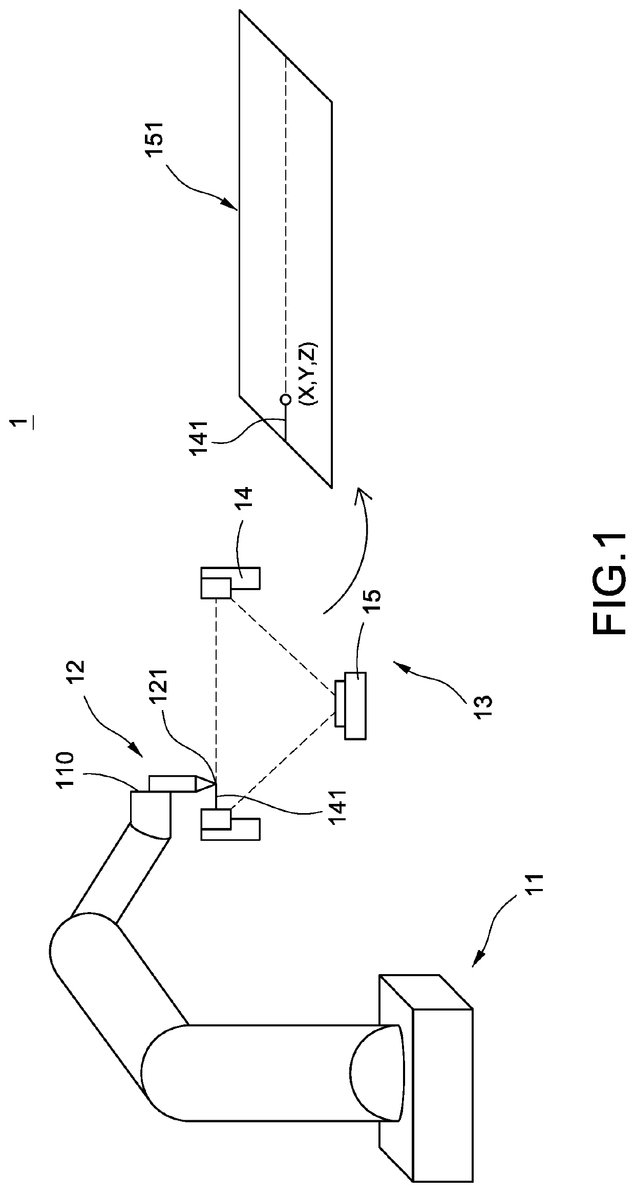
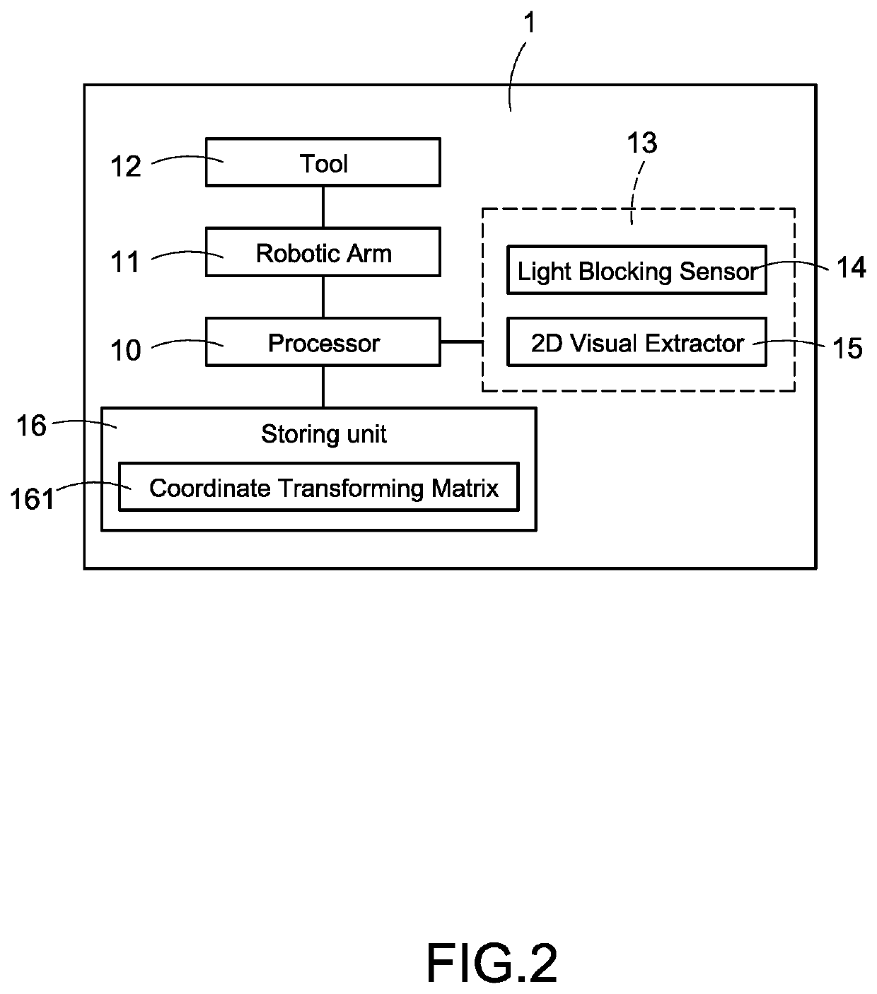
[0041]FIG. 1 is a schematic diagram of a calibration apparatus of a first embodiment according to this disclosure. FIG. 2 is a block diagram of a calibration apparatus of a first embodiment according to this disclosure.

[0042]As shown in FIG. 1 and FIG. 2, this disclosure discloses a calibration apparatus 1, the calibration apparatus 1 may be used to calibrate a coordinate system used by a robotic arm 11. In particular, different parts of the robotic arm 11 may respectively use different coordinate systems to perform positioning, and different robotic arms may also use different coordinate systems. The calibration apparatus 1 of this disclosure may perform alignment and calibration to different coordinate systems for eliminating the position deviations among them, so the robotic arm 11 may be trustworthy in performing high precision tasks.

[0043]As shown in FIG. 1 and FIG. 2, the calibration apparatus 1 may have a processor 10, the robotic arm 11 and an alignment device 13. The roboti...

second embodiment

[0059]Please refer to FIG. 14, which is a schematic diagram of a calibration apparatus of a second embodiment according to this disclosure. In the embodiment as shown in FIG. 14, the calibration apparatus 1 includes a processor (not shown), the robotic arm 11, and another alignment device 13′. In this embodiment, the alignment device 13′ is a 3D machine visual sensor.

[0060]In particular, the 3D machine visual sensor is a type of sensor which may directly capture a 3D image within a three-dimensional space 131. When the robotic arm 11 drives the tool 12 to move within the three-dimensional space 131, the alignment device 13′ may directly capture a 3D image of the tool 12, and perform an image analysis to the 3D image, therefore the processor may obtain information of the tool 12, such as shape, gesture, position, tilted angle, etc. through the analyzed data obtained from the image analysis. Besides, after corresponding the analyzed data to the alignment device coordinate system AF us...


PUM


Abstract

A calibration apparatus includes a processor, an alignment device, and an arm. The alignment device captures images in a three-dimensional space, and a tool is arranged on a flange of the arm. The processor records a first matrix of transformation between an end-effector coordinate-system and a robot coordinate-system, and performs a tool calibration procedure according to the images captured by the alignment device for obtaining a second matrix of transformation between a tool coordinate-system and the end-effector coordinate-system. The processor calculates relative position of a tool center point of the tool in the robot coordinate-system based on the first and second matrixes, and controls the TCP to move in the three-dimensional space for performing a positioning procedure so as to regard points in an alignment device coordinate-system as points of the TCP, and calculates the relative positions of points in the alignment device coordinate-system and in the robot coordinate-system.

Description

BACKGROUND OF THE INVENTION1. Technical Field[0001]The technical field relates to a robotic arm, and specifically relates to a calibration apparatus and a calibration method for calibrating a coordinate system of the robotic arm.2. Description of Related Art[0002]For ensuring that a robotic arm can work on the precise position, the operator of the robotic arm needs to calibrate the robotic arm as well as a tool arranged thereon after the tool is assembled, or is using for a long period, or is changed, etc. Especially, the coordinates of a tool center point (TCP) of the tool need to be calibrated.[0003]Common styles of calibration apparatus in the market use infrared emitter to emit infrared light to a closed area, and control the robotic arm to move, via the TCP of the tool arranged on the robotic arm, in the closed area for blocking the infrared light, so as to perform a point teaching action of the TCP and then creates a tool pattern of the tool.[0004]After the tool is used for a ...

Claims


Application Information

Patent Timeline
Patent Type & Authority Applications(United States)
IPC IPC(8): B25J9/16B25J9/02B25J13/08
CPCB25J9/1692B25J9/1697B25J13/088B25J9/023B25J9/1607B25J9/1664G05B2219/39022G05B2219/39007G05B2219/39025G01B11/002Y02P90/02
Inventor HUANG, CHENG-HAOWANG, SHI-YUHUANG, PO-CHIAOLIN, HAN-CHINGLI, MENG-ZONG
Owner DELTA ELECTRONICS INC
Learn More