
High-speed radiated spurious emission automated test system and method thereof

a spurious emission and automated testing technology, applied in the field of rse test, can solve the problems of large test space, high cost, limited sampling test, etc., and achieve the effect of significantly reducing investigation and measurement time and effective reducing the time for investigation

Active Publication Date: 2021-11-23
SPORTON INT INC
View PDF0 Cites 3 Cited by
  • Summary
  • Abstract
  • Description
  • Claims
  • Application Information

AI Technical Summary

Benefits of technology

The present invention provides a fast and automated system for testing spurious emissions in the 1-40 GHz range. It integrates a test system and software to streamline the process and reduce investigation and measurement time. This system can simulate the results of anechoic chambers and significantly reduce the time required for investigation and measurement.

Problems solved by technology

However, both of DFF test and radiative near field test have the shortcomings of long test time, large test space, high cost, being limited to sampling test, etc.
On the other hand, IFF test also has some shortcomings; for example, IFF test requires multiple point tests, needs long time for a single test and is not applicable to batching test in production lines.
The shortcoming of the fully anechoic chamber is of high cost, so the test space is limited.
Thus, if the RSE test is implemented via a semi / fully anechoic chamber, the time needed by the RSE test will be long, which may be up to several weeks.
Obviously, the currently available technologies still have some shortcomings in the implementation of the RSE test, so cannot satisfy the test requirements of wireless communication products in high-speed development.
Accordingly, it has become an important issue for the industry to improve currently available technologies.

Method used


Image

  • High-speed radiated spurious emission automated test system and method thereof
  • High-speed radiated spurious emission automated test system and method thereof
  • High-speed radiated spurious emission automated test system and method thereof

Examples


Embodiment Construction

[0029]The following description is about embodiments of the present invention; however it is not intended to limit the scope of the present invention.

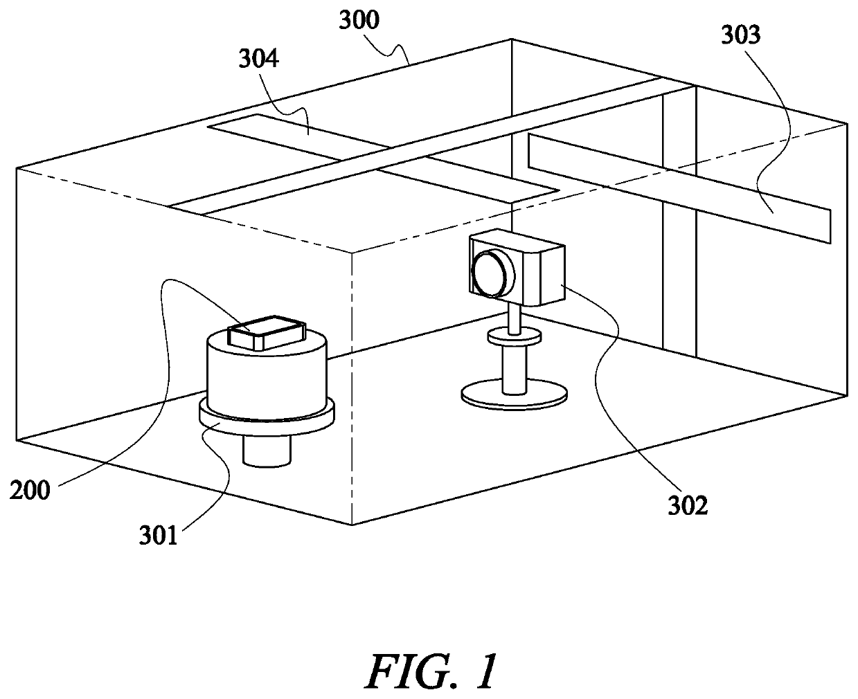
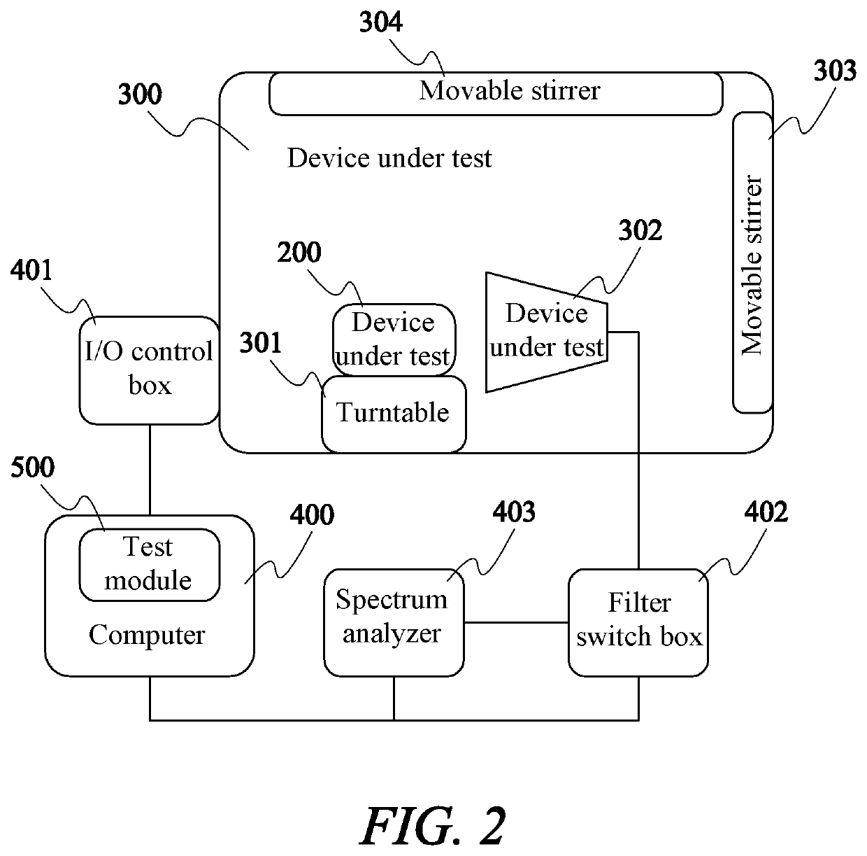
[0030]Please refer to FIG. 1 and FIG. 2, which are a perspective view and a structural block diagram of a high-speed radiated spurious emission (RSE) automated test system in accordance with the present invention. The high-speed RSE automated test system mainly includes a device under test (DUT) 200, a RSE test chamber (RTC) 300, a computer 400 for controlling and analysis and some relevant test elements thereof. The RSE test chamber 300 includes a turntable (TT) 301, a receiving antenna (RXA) 302 and two movable stirrers (MS) 303, 304 disposed therein. The DUT 200 is disposed on the turntable 301 and can rotate according to the operation mode selected based on the measurement requirement to adjust the direction of the DUT 200. One side of the receiving antenna 302 faces the turntable 301 in order to receive the RSE test signal from th...


PUM


Abstract

A high-speed RSE automated test system includes a RSE test chamber and a computer. The RSE test chamber includes a turntable disposed therein and a DUT is disposed on the turntable. The RSE test chamber further includes a receiving antenna configured to receive a RSE test signal from the DUT. The RSE test chamber further includes a movable stirrer configured to simulate the measurement environment of semi / fully anechoic chamber. The computer is connected to an I / O control box configured to control the movable stirrer and the turntable. The computer is further connected to a filter switch box configured to transmit the RSE test signal to a spectrum analyzer to obtain a measured value. The computer includes a test module with all necessary parameters for the RSE test and the test module is configured to generate an integrated test result.

Description

BACKGROUND OF THE INVENTION1. Field of the Invention[0001]The present invention relates to the radiated spurious emission (RSE) test field, in particular to a test system integrated with an automated test software to effectively reduce the time for investigation and measurement of RSE between 1˜40 GHz in order to obtain the RSE measurement results of simulating semi / fully anechoic chambers and significantly reducing investigation and measurement time.2. Description of the Prior Art[0002]With advance of technology, various new wireless communication products are developed, which adopt more technologies about bandwidth / modulation / aggregated wave . . . ; for the reason, many test modes should be investigated and performed.[0003]Radiated spurious emission (RSE) test is an important item in the certification of wireless communication products. The currently available RSE test mainly includes: direct far field (DFF) test; indirect far field (IFF) test and radiative near field test. Howeve...

Claims


Application Information

Patent Timeline
IPC IPC(8): G06F11/36
CPCG06F11/3684G06F11/368G06F11/3692G01R29/0828
Inventor CHANG, HSUAN-CHIYAO, CHIN-HONG
Owner SPORTON INT INC
Learn More