
Ignition insert with an active pre-chamber

a technology of active prechamber and ignition insert, which is applied in the direction of pistons, machines/engines, engine components, etc., can solve the problems of large radial space requirement, difficult to create very small volume prechambers, and inability to integrate active prechambers, etc., and achieves the effect of low cost and inexpensive manufacturing

Active Publication Date: 2021-11-30
RABHI VIANNEY
View PDF39 Cites 0 Cited by
  • Summary
  • Abstract
  • Description
  • Claims
  • Application Information

AI Technical Summary

Benefits of technology

This design enables efficient and cost-effective implementation of active pre-chambers in various engines, reducing fuel consumption and thermal losses while maintaining engine efficiency and reducing the need for extensive modifications.

Problems solved by technology

One of the difficulties in installing the active ignition pre-chambers is the space occupied by the spark plug and the injector which the said pre-chambers receive, and which open into the very small volume of the said pre-chambers.
FR 3 061 743, as it is difficult to propagate the flame previously initiated in the pre-chamber by the spark plug in such a duct, the latter being cold, blocking the flame, forming a trap for unburnt residues, and strongly cooling the pilot charge due to the large internal surface that it exposes in relation to its volume.
Active pre-chambers thus pose a problem of integration in internal combustion engines, since the spark plug and the injector are usually placed next to each other or almost next to each other, as shown for example by patent EP 3 001 008 A1.
This arrangement results in a substantial radial space requirement for the pre-chamber, spark plug and injector assembly.
Moreover, this arrangement makes it difficult to create very small volume pre-chambers without the internal surface / volume ratio of the pre-chambers being very large and favours excessive cooling of the pilot charge gases once the latter have been heated to high temperature.
In addition, cooling of the pre-chamber becomes potentially difficult to achieve if it is not in direct contact with the cooling water circulating in the water chambers of the cylinder head.
It should also be noted that installing an active pre-chamber in a pre-existing engine requires extensive modifications to the cylinder head, as the cylinder head cannot accommodate the active pre-chamber without substantial modifications.

Method used


Image

  • Ignition insert with an active pre-chamber
  • Ignition insert with an active pre-chamber
  • Ignition insert with an active pre-chamber

Examples


Embodiment Construction

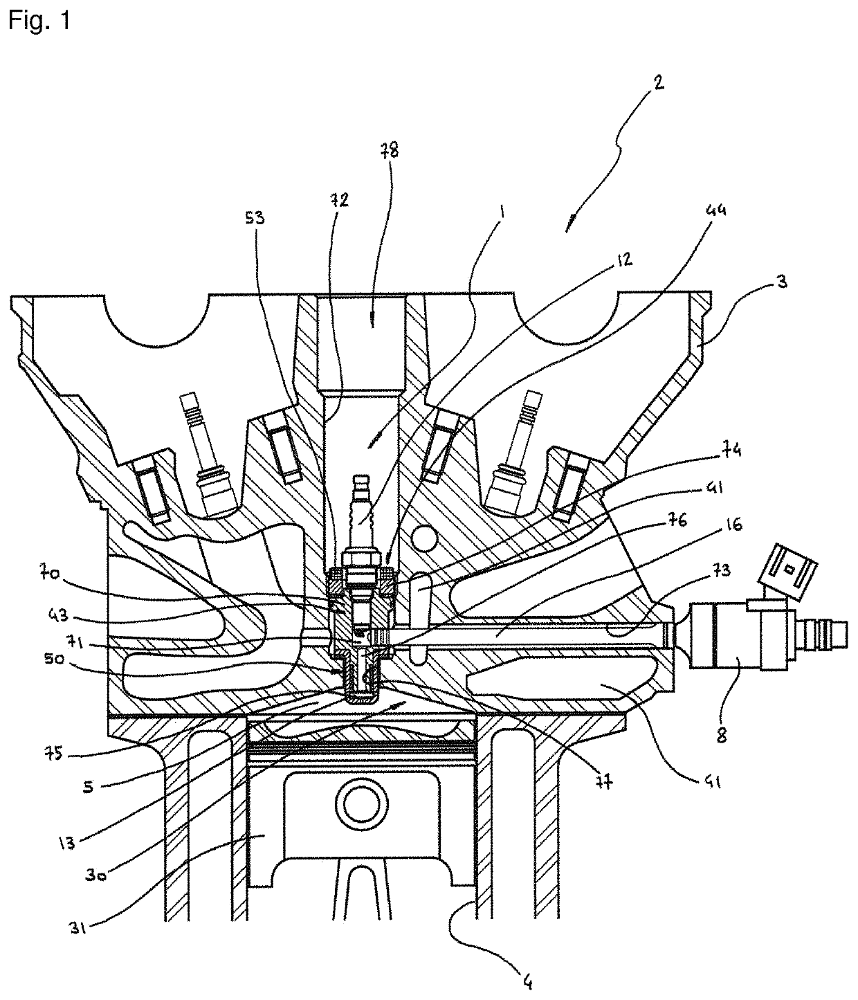
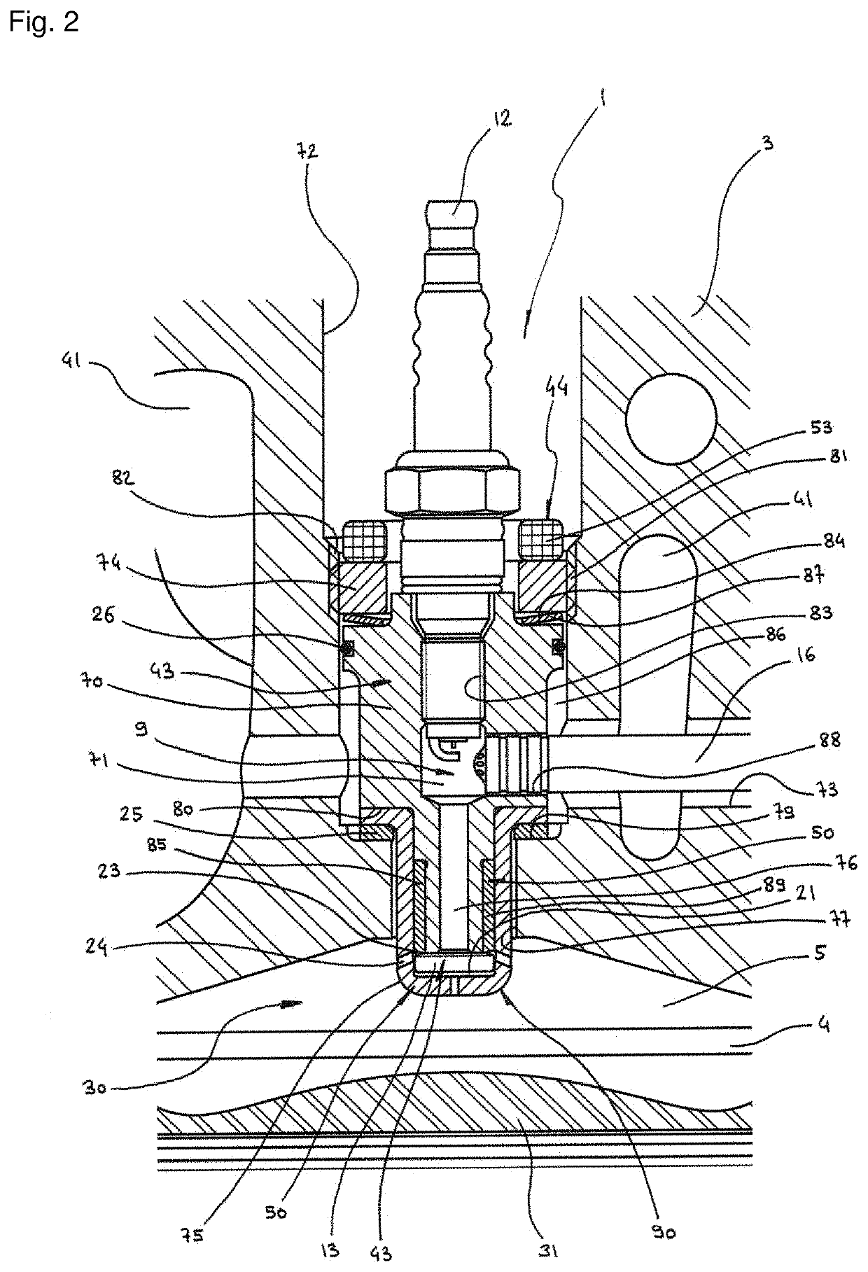
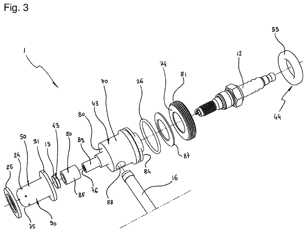
[0052]FIGS. 1 to 6 show the ignition insert with an active pre-chamber 1 according to the invention, various details of its components, its alternative embodiments, and its accessories.

[0053]The ignition insert with active pre-chamber 1 is particularly provided for an internal combustion engine 2, the latter comprising a cylinder head 3 which covers a cylinder 4 to form with a piston 31 a combustion chamber 5 into which can be introduced a main load 30.

[0054]As can be seen in FIGS. 1, 2, 5 and 6, the cylinder head 3 houses an ignition pre-chamber 71 in which open a spark plug 12 and an injector nose 16 of at least one injector 8 and into which a pilot charge 9 can be introduced, said pre-chamber 71 being capable to communicate with the combustion chamber 5 successively via a gas ejection conduit 76 and via at least one gas ejection orifice 24 which opens into said chamber 5 via a pre-chamber nose 75.

[0055]As can be seen in FIGS. 1, 2, 5 and 6, the ignition insert with an active pre-...


PUM


Abstract

The ignition insert with an active pre-chamber (1) comprises an insert well (72) arranged in a cylinder head (3) of an internal combustion engine (2), said well (72) accommodating a cylindrical insert body (70) which is indexed in rotation and in which are arranged an ignition pre-chamber (71), an insert spark plug well (83) receiving a spark plug (12), and a injector radial orifice (88) which is aligned with a injector lateral well (73) arranged in the cylinder head (3) so as to receive an injector nose (16), said body (70) being terminated by a pre-chamber nose (75) opening into a combustion chamber (5), and being held in the insert well (72) by fixing means (82) cooperating with clamping means (74).

Description

FIELD OF THE INVENTION[0001]The present invention relates to an ignition insert with an active pre-chamber which makes it possible to accommodate an active pre-chamber in the cylinder head of an internal combustion engine in a small space and in a minimally intrusive manner.BACKGROUND OF THE INVENTION[0002]There are many concepts of active pre-chambers, the latter being used as an ignition means for igniting a main charge in the combustion chamber of an internal combustion engine.[0003]The term “active” pre-chamber is commonly used to describe pre-chambers into which opens, in addition to a known electric spark plug, at least one fuel injector with or without an air injector or at least one fuel-air mixture injector.[0004]For example, the concept is known of a pre-chamber known as “Turbulent Jet Ignition”, patented and developed by the “Mahle” company. This concept—which was the subject of patent EP 3 001 008 A1 published on 30 Mar. 2016—provides for a pre-chamber into which opens a...

Claims


Application Information

Patent Timeline
Patent Type & Authority Patents(United States)
IPC IPC(8): F02B19/12F02B19/18F02B19/02F02F3/00F02F1/24F02B19/10
CPCF02B19/12F02B19/02F02B19/108F02B19/18F02F1/24F02F3/00F02B19/10F02B19/1004F02B19/1009F02B19/1014F02B19/1019F02B19/1071F02F1/242Y02T10/12
Inventor RABHI, VIANNEY
Owner RABHI VIANNEY
Learn More