Hydrodynamic vortex aspiration catheter

a technology of aspiration catheter and a vortex, which is applied in the field of catheters, can solve the problems of vascular damage, distal embolization of clots, and largely ineffective systemic delivery of drugs, and achieves rapid and effective thromboplasty, safe and efficient intravascular navigation, and high efficiency and effective interventions.

Active Publication Date: 2021-12-07
RGT UNIV OF MICHIGAN
View PDF96 Cites 0 Cited by
  • Summary
  • Abstract
  • Description
  • Claims
  • Application Information

AI Technical Summary

Benefits of technology

[0006]Modification of catheter shape has been suggested or disclosed in the prior art to enhance aspiration of intravascular clots. In U.S. Pat. No. 8,075,510 to Aklog et al., a suction cannula is described with a distal end that is deployable to expand from a first diameter to a relatively larger second diameter with a funnel shape. The differential diameter is believed to induce a laminar flow circumferentially along the interior surface of the funnel to generate a vortex flow into the distal end of suction cannula. In the presence of a vortex flow, such a flow can act to direct the undesirable material toward the distal end to allow the material to subsequently be pulled into the distal end by suctioning.
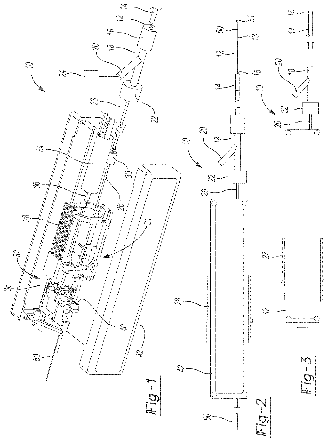
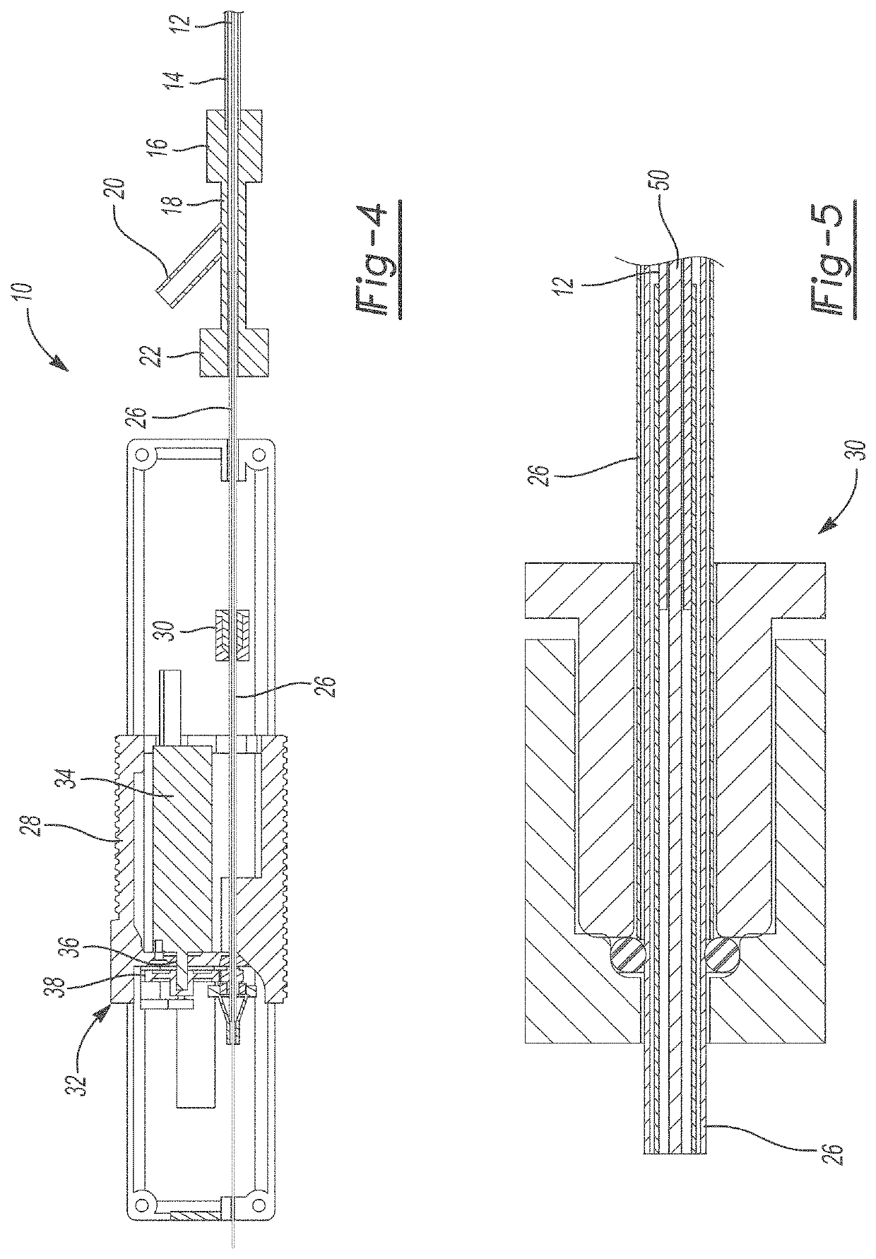
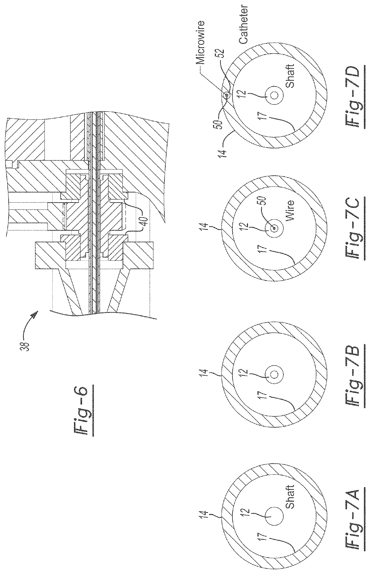
[0159]In some embodiments, shaft 12 can be rotated at high speed outside (e.g. beyond) distal end 15 of catheter 14 following orbital movements that extend along a path that can be larger than the diameter of catheter 14. The diameter of this orbital movement of shaft 12 outside catheter 14 is dependent upon the rotational speed, the length of shaft 12 protruding outside catheter 14, the ID of catheter 14, and the flexibility of shaft 12. The translational movement of a shaft 12 with enough stiffness to act as cutting tool will generate a cutting cone to fragment tissues and clots 100. This can be coupled with vacuum to removed fragmented debris. This can be coupled by a bipolar mechanism (between an electrified shaft or shaft tip and catheter 14 distal-most opening) to induce bipolar current and simultaneous coagulation during tissue maceration. This can also be coupled to hollow channel 52 along the wall of catheter 14 that enables a fluid media to be delivered at or near the distal end of catheter 14 which can then backfill the lumen of catheter 14 via vacuum. This would enable the generation of hydraulic forces and translational shaft motions when catheter 14 is not already immersed into a liquid environment.

Problems solved by technology

The formation of a thrombus can occur within the heart or any artery or vein in the body, leading to a myriad of medical problems such as myocardial infarction, stroke, pulmonary embolism, and deep venous thrombosis.
Rapid thrombectomy is frequently needed in cases of 1) obstruction of arteries of delicate organs, such as the heart or the brain; 2) large clots interrupting blood flow in major vessels or causing severe symptoms; or 3) when systemic delivery of the drugs is too risky.
However, these devices continue to be largely ineffective with large clot burden, “organized” (i.e. thick) clots, and clots extending from large to small vessels, and many such devices cause distal embolization of clots and vascular damage as they dispose the cutting or macerating mechanism directly into the vascular lumen.
Mechanical thrombectomy in stroke presents additional challenges based on the tortuosity of vessel and the delicate nature of vessel walls.
In this regard, mechanical thrombectomy mechanisms that have been successfully used in the peripheral vasculature to remove clots, some of which are described below, are too bulky and stiff for navigating the complex cerebral artery geometries, release many clot particles downstream leading to microvascular occlusion, or are too abrasive for delicate brain arterial walls.
The abovementioned devices are not intended to pass through tortuous pathways found in the fragile brain vessels as they would release clot material downstream leading to strokes, or the actuation of the macerating mechanism disposed directly in the vascular lumen would lead to vascular damage of delicate vessels.
The required stiffness of the rotatory elements in this prior art, along with the inability to be co-axially navigated over an inner guidewire, would preclude its use for atraumatic navigation within the vasculature beyond the tip of the aspiration catheter.
Additionally, the required stiffness of the rotary element creates large radial forces against the inner wall of the catheter, leading to high friction and rapid wear of the catheter.
The prior art does not disclose a stand-alone device suitable for both navigation into narrow and highly tortuous vasculature and the ability to clear occlusive material by rotatory-induced hydrodynamic vortices.
Such a technology would be challenging to develop as the features needed for safe intravascular navigation are generally contraposed to the features needed for efficient clot removal.

Method used


Image

  • Hydrodynamic vortex aspiration catheter
  • Hydrodynamic vortex aspiration catheter
  • Hydrodynamic vortex aspiration catheter

Examples


Embodiment Construction

[0055]Example embodiments will now be described more fully with reference to the accompanying drawings. Example embodiments are provided so that this disclosure will be thorough, and will fully convey the scope to those who are skilled in the art. Numerous specific details are set forth such as examples of specific components, devices, and methods, to provide a thorough understanding of embodiments of the present disclosure. It will be apparent to those skilled in the art that specific details need not be employed, that example embodiments may be embodied in many different forms and that neither should be construed to limit the scope of the disclosure. In some example embodiments, well-known processes, well-known device structures, and well-known technologies are not described in detail.

[0056]The terminology used herein is for the purpose of describing particular example embodiments only and is not intended to be limiting. As used herein, the singular forms “a,”“an,” and “the” may b...


PUM


Abstract

An actuated telescoping system for navigation within a vascular lumen and thrombectomy of a thrombus. The system includes a tubular catheter member having an open distal end defining a catheter lumen, a vacuum source, a rotational drive system, a flexible shaft having a channel coupled to the rotational drive system for rotational movement in response thereto, and an optional guidewire selectively inserted at least partially within the flexible shaft. The flexible shaft is at least partially disposed within the tubular catheter member configured for uncoupled rotational and translational motion therein and to optionally define a corkscrew motion in response to rotational driving force by the drive system that results in formation of hydrodynamic vortices within the catheter lumen. The telescoping system can be capable of reversibly transitioning between navigation and thrombectomy modes by differentially disposing and actuating the components and enable faster, more efficient and simpler removal of thromboembolic material.

Description

CROSS-REFERENCE TO RELATED APPLICATIONS[0001]This application is a continuation of PCT International Application No. PCT / US2019 / 026737, filed on Apr. 10, 2019, which is a continuation-in-part application of U.S. patent application Ser. No. 16 / 156,519, filed Oct. 10, 2018, which is a continuation-in-part application of PCT International Application No. PCT / US2018 / 026831, filed on Apr. 10, 2018, which claims the benefit of U.S. Provisional Application No. 62 / 483,580, filed on Apr. 10, 2017. This application is also a continuation-in-part of U.S. patent application Ser. No. 16 / 156,519, filed Oct. 10, 2018. The entire disclosures of each of the above applications are incorporated herein by reference.FIELD[0002]The present disclosure relates to catheters and, more particularly, relates to an aspiration catheter augmented by hydrodynamic vortices that are generated by high-speed rotation of a flexible shaft.BACKGROUND AND SUMMARY[0003]This section provides background information related t...

Claims


Application Information

Patent Timeline
Patent Type & Authority Patents(United States)
IPC IPC(8): A61B17/3207A61B17/22A61B17/00
CPCA61B17/320758A61B17/22A61B2017/00685A61B2017/00991A61B2017/22045A61B2017/22079A61B2017/320766A61B2217/005A61B2217/007A61B17/3207A61B17/320725A61B2017/22038A61B2017/22039A61B2017/22044A61M2025/0073A61M2206/16A61M2206/20A61M1/842
Inventor SAVASTANO, LUIS EMILIOPLOTT, JEFFREY STEPHENLIU, YANGZHENG, YIHAOSHIH, ALBERT JAU-MIN
Owner RGT UNIV OF MICHIGAN
Why Eureka
Try Eureka