
Image forming apparatus and image forming method

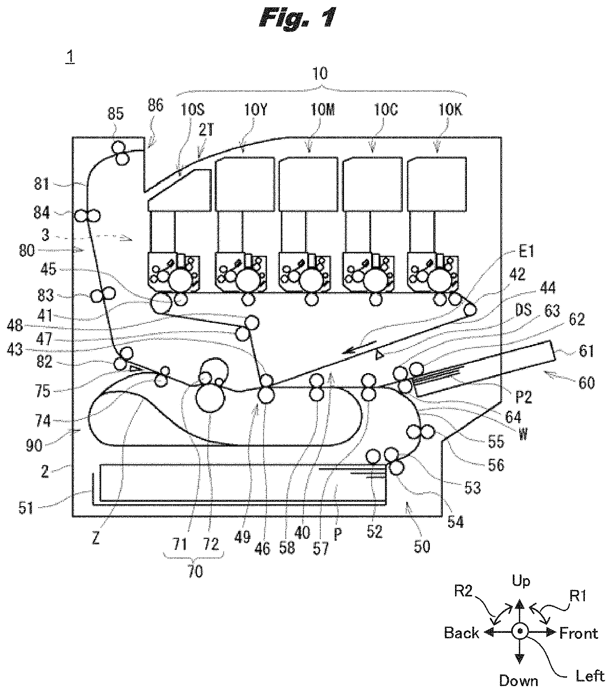
a technology of image forming and forming apparatus, which is applied in the direction of electrographic process apparatus, instruments, developers, etc., can solve the problems of decreasing brilliance and achieve the effect of decreasing color reproducibility and decreasing brillian

Active Publication Date: 2021-12-07
OKI ELECTRIC IND CO LTD
View PDF4 Cites 0 Cited by
  • Summary
  • Abstract
  • Description
  • Claims
  • Application Information

AI Technical Summary

Benefits of technology

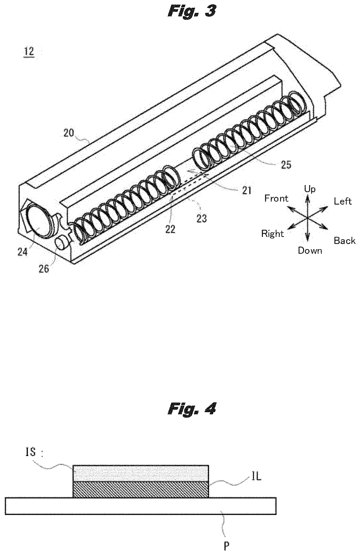
[0011]Because this invention performs a control so as to determine a brilliant deposition amount MS according to the color and color deposition amount ML of a color toner, it can prevent the color toner from becoming too much, causing a brilliant toner to be buried in the color toner, and decreasing brilliance, or becoming too little and decreasing color reproducibility.
[0012]This invention can realize an image forming apparatus and an image forming method that achieve both color reproducibility with color toners and brilliance with a brilliant toner.

Problems solved by technology

However, there was a problem in an image forming apparatus that when expressing a dark color by increasing the deposition amount of the color toner per unit area, even if the coverage is set within the prescribed range, part of the brilliant toner superimposed on the color toner may be buried in the color toner, decreasing brilliance.

Method used


Image

  • Image forming apparatus and image forming method
  • Image forming apparatus and image forming method
  • Image forming apparatus and image forming method

Examples


embodiment 1

2-1. Embodiment 1

[0087]In this Embodiment 1, generated was an aqueous medium where an inorganic dispersant was dispersed. Specifically, industrial trisodium phosphate dodecahydrate 919 pts. wt. were added to pure water 26526 pts. wt., dissolved at liquid temperature 60 [° C.], and afterwards dilute nitric acid was added for adjusting pH (hydrogen-ion exponent). Added to this solution was a calcium chloride solution where industrial anhydrous calcium chloride 443 pts. wt. were dissolved in pure water 4504 pts. wt., and keeping its liquid temperature at 60 [° C.], it was high-speed stirred for 34 minutes by a line mill (manufactured by PRIMIX Corporation) at a rotation speed of 3566 [rpm]. Thereby, prepared was a water phase that was an aqueous medium where a suspension stabilizer (inorganic dispersant) was dispersed.

[0088]Next, in Embodiment 1, a pigment-dispersed liquid was generated. Specifically, mixed with ethyl acetate 7427 pts. wt. were a brilliant pigment 394 pts. wt. and a ch...

embodiment 2

2-3. Embodiment 2

[0096]In Embodiment 2, although generally the same procedures as in Embodiment 1 were followed, by changing the brilliant pigment quantity to 173 pts. wt., the brilliant toner TSc was prepared

embodiment 3

2-4. Embodiment 3

[0097]In Embodiment 3, although generally the same procedures as in Embodiment 1 were followed, by changing the brilliant pigment quantity to 251 pts. wt., the brilliant toner TSd was prepared


PUM


Abstract

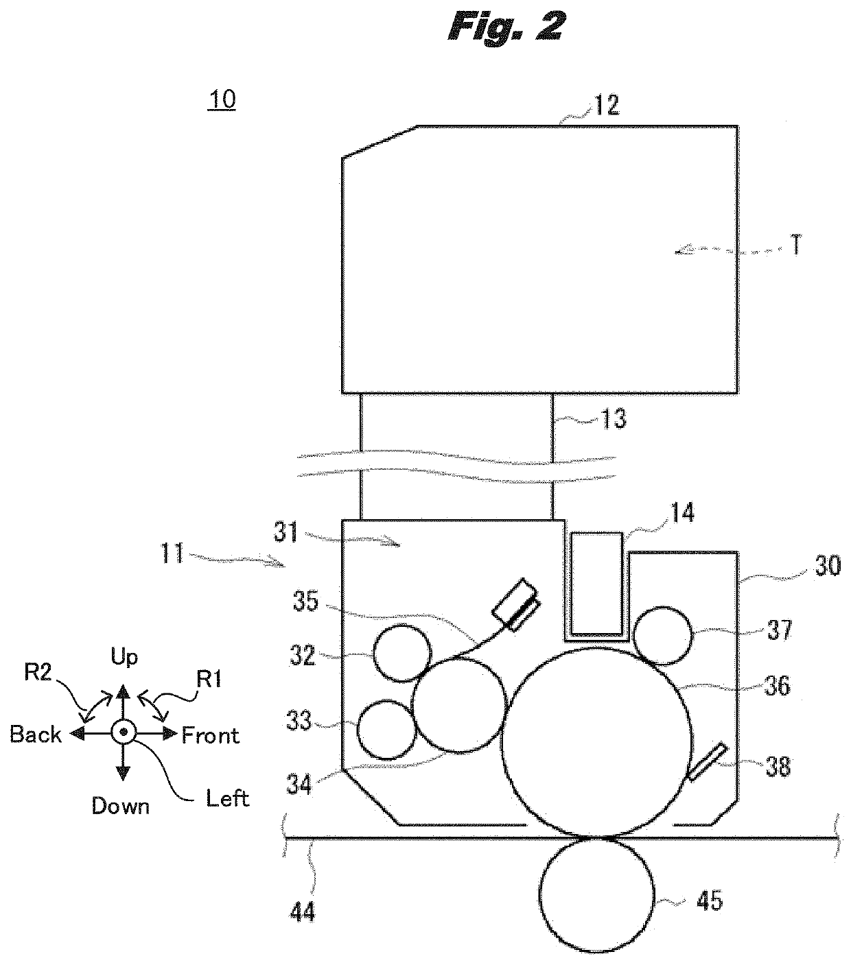
An image forming apparatus includes a brilliant image forming part that forms a brilliant toner image using a brilliant toner, a color image forming part that forms a color toner image using a color toner, and a controller that controls a brilliant deposition amount of the brilliant toner and a color deposition amount of the color toner on a medium, wherein when the brilliant toner image is to be superimposed over the color toner image on the medium, the controller adjusts the brilliant deposition amount for the brilliant toner image in correspondence with a color type and the color deposition amount of the color toner that has been used for the color toner image.

Description

TECHNOLOGY FIELD[0001]This invention relates to an image forming apparatus and an image forming method that are suitable for applying to an electrophotographic printer for example.BACKGROUND[0002]Conventionally, widely used as an image forming apparatus (also called a printer) is one that performs a print process by forming a toner image by an image forming unit using a toner (also called a developer) based on an image supplied from a computer device etc., transfers it onto a medium such as a sheet of paper, and fusing it by applying heat and pressure. In an image forming apparatus, when performing general color printing, for example, toners of individual colors such as cyan, magenta, yellow, and black (these are hereafter called color toners) are used.[0003]Also, among image forming apparatuses there is one that forms an image with high brilliance similar to metallic luster by superimposing a brilliant toner containing a metallic pigment such as aluminum on color toners. Further pr...

Claims


Application Information

Patent Timeline
Patent Type & Authority Patents(United States)
IPC IPC(8): G03G15/00G03G9/09G03G15/01G03G9/08
CPCG03G9/0926G03G9/0819G03G9/0827G03G15/0121G03G2215/00029G03G15/6585
Inventor MATSUMOTO, HAYATO
Owner OKI ELECTRIC IND CO LTD
Learn More