Unlock instant, AI-driven research and patent intelligence for your innovation.

CCUS (carbon capture utilization and storage) system for exploiting thickened oil reservoirs based on optimal flue gas CO2 enrichment ratio and working method thereof

a technology of flue gas co2 enrichment and utilization and storage system, which is applied in the direction of indirect carbon-dioxide mitigation, lighting and heating apparatus, borehole/well accessories, etc., can solve the problems of high co2 discharge and contrary to fulfillment, and achieve the effect of reducing the energy consumption of the co2 capturing link and reducing the energy consumption of the air separation oxygen preparation

Active Publication Date: 2021-12-28
CHINA UNIV OF PETROLEUM (EAST CHINA)
View PDF3 Cites 0 Cited by
  • Summary
  • Abstract
  • Description
  • Claims
  • Application Information

AI Technical Summary

Benefits of technology

[0009]The invention further promotes large-scale application of the CCUS technology in the field of thickened oil thermal production, changes CO2 capturing into CO2 enrichment, realizes the reduction of the CO2 capturing energy consumption and improvement of the CO2 oil-driving effect synergistically, and further realizes cost reduction and effect increase of the whole CCUS process.
[0037]1. The formed CCUS system, compared with the traditional CCUS system and process, realizes the direct injection of boiler flue gas after purification based on real-time adjustment of the flue gas CO2 enrichment ratio and greatly reduces the energy consumption in the CO2 capturing link in the CCUS process as CO2 capturing is changed into flue gas CO2 enrichment.
[0038]2. The CCUS system determines the optimal oxygen-including concentration of the boiler injection gas based on the needed optimal flue gas CO2 enrichment since a two-stage air film separation system is adopted, further realizes real-time adjustment of the oxygen-rich air oxygen concentration needed by air film separation, avoids 100% oxygen enrichment needing oxygen preparation through air film separation in a conventional oxygen-rich combustion process, and further reduces the energy consumption of the air separation oxygen preparation link.
[0040]4. The CCUS system can realize analysis of the storage and retention of the flue gas injected in the early stage based on component monitoring of the gas produced by the thermal production well group, and can carry out gas component injection and flow adjustment through the boiler combustion when the CO2 proportion in the produced gas is relatively high, can realize re-injection of the partial produced gas into the boiler and further into the thickened oil reservoir through the boiler combustion injection gas component and flow adjustment, can reduce CO2 discharge and can realize underground storage.

Problems solved by technology

High amounts of CO2 discharge is contrary to the fulfillment of a carbon emission reduction promise of China.

Method used


Image

  • CCUS (carbon capture utilization and storage) system for exploiting thickened oil reservoirs based on optimal flue gas CO<sub>2 </sub>enrichment ratio and working method thereof

Examples


embodiment 1

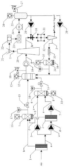
[0047]A CCUS system for exploiting the thickened oil reservoir based on the optimal flue gas CO2 enrichment ratio comprises a flue gas CO2 enrichment unit, a flue gas injection unit, a thickened oil thermal production well group unit and a produced gas recovery unit;

[0048]the fuel gas CO2 enrichment unit comprises an air separating enrichment unit and a boiler injection gas premixed tank 15;

[0049]the air separating enrichment unit comprises:

[0050]an air separating primary device used for separating air into oxygen and nitrogen preliminarily;

[0051]an air separating secondary device used for further enriching a part of the oxygen which is subjected to the preliminary separation;

[0052]the boiler injection gas premixed tank 15 is used for mixing the preliminarily separated nitrogen, the preliminarily separated part of the oxygen and / or the further enriched oxygen.

embodiment 2

[0053]According to the CCUS system for exploiting the thickened oil reservoir based on the optimal flue gas CO2 enrichment ratio of Embodiment 1, the difference is that the air separating primary device comprises the air film separating primary device 1, the nitrogen-rich conveying pipeline b, the first oxygen-rich conveying pipeline a; the nitrogen-rich air conveying pipeline b is connected with the nitrogen-rich gas pressurization monitoring tank 7; and the first oxygen-rich air conveying pipeline a is connected with the oxygen-rich gas pressurization monitoring tank 6 through the second oxygen-rich air conveying pipeline c.

[0054]The air separating secondary device comprises the air film separating secondary device 2; and the first oxygen-rich air conveying pipeline a is connected with the oxygen-rich gas pressurization monitoring tank 6 through the third oxygen-rich air conveying pipeline d and the air film separating secondary device 2.

embodiment 3

[0055]According to the CCUS system for exploiting the thickened oil reservoir based on the optimal flue gas CO2 enrichment ratio of Embodiment 1, the difference is that the flue gas injection unit comprises a boiler connected with the boiler injection gas premixed tank 15 through the boiler injection gas pressure stabilizer 19; and the flue gas outlet of the boiler is connected with the flue gas monitoring tank 25 through the boiler flue gas conveying pipeline I.

[0056]The boiler flue gas conveying pipeline I is provided with the flue gas dust remover 21, the flue gas dehumidifier 22, the flue gas desulfurization and denitrification device 23 and the flue gas compressor 24.


PUM


Abstract

A CCUS system for exploiting a thickened oil reservoir based on an optimal flue gas CO2 enrichment ratio. The CCUS system comprises a flue gas CO2 enrichment unit, a flue gas injection unit, a thickened oil thermal production well group unit and a produced gas recovery unit; the fuel gas CO2 enrichment unit comprises an air separating enrichment unit and a boiler injection gas premixed tank; the air separating enrichment unit comprises an air separating primary device used for separating air into oxygen and nitrogen preliminarily, and an air separating secondary device used for further enriching a part of the oxygen which is subjected to the preliminary separation; and the boiler injection gas premixed tank is used for mixing the preliminarily separated nitrogen, the preliminarily separated part of the oxygen and / or the further enriched oxygen.

Description

BACKGROUND OF THE INVENTIONTechnical Field[0001]The invention relates to a Carbon Capture Utilization & storage (CCUS) system for exploiting a thickened oil reservoir based on an optimal flue gas CO2 enrichment ratio and a working method thereof and belongs to the technical field of thickened oil thermal production and CO2 gathering, utilization and buried storage.Description of Related Art[0002]Action Plan for Energy Technology Revolution and Innovation (2016-2030), jointly issued by NDRC (National Development and Reform Commission) and National Energy Administration in Apr. 2016, defines the overall goals of Chinese revolution in energy technology, including two significant tasks: “clean and efficient coal utilization technology innovation” and “CO2 capturing, utilization and storage technology innovation”, and aims at greatly reducing pollutant discharge in the energy production process greatly, providing a more environment-friendly energy technology support and building a green ...

Claims


Application Information

Patent Timeline
Patent Type & Authority Patents(United States)
IPC IPC(8): E21B43/16E21B43/40E21B41/00
CPCE21B41/0064E21B43/164E21B43/40E21B43/16F23J15/00F23J15/02F23L7/00Y02P90/70E21B43/24E21B43/2408Y02C20/40Y02E20/32Y02E20/34
Inventor ZHANG, CHAOLI, ZHAOMINLIU, JIANLINZHAO, DONGYALU, TENGWU, SHOUYAGUO, LONGJIANG
Owner CHINA UNIV OF PETROLEUM (EAST CHINA)