Cooking appliance comprising a receiving area for a removable sensor module

Active Publication Date: 2022-01-18
BSH BOSCH & SIEMENS HAUSGERAETE GMBH
View PDF12 Cites 0 Cited by
  • Summary
  • Abstract
  • Description
  • Claims
  • Application Information

AI Technical Summary

Benefits of technology

[0004]Object of the invention is to improve the operation of sensors in the food to be cooked, in particular to arrange the sensor securely in the cooking appliance such as to meet the user demands

Problems solved by technology

In the closed operating position of the door, the receptacle is concealed by components of the cooking applian

Method used


Image

  • Cooking appliance comprising a receiving area for a removable sensor module
  • Cooking appliance comprising a receiving area for a removable sensor module

Examples


Example

[0027]In the figures, same or functionally identical elements are provided with the same reference characters.

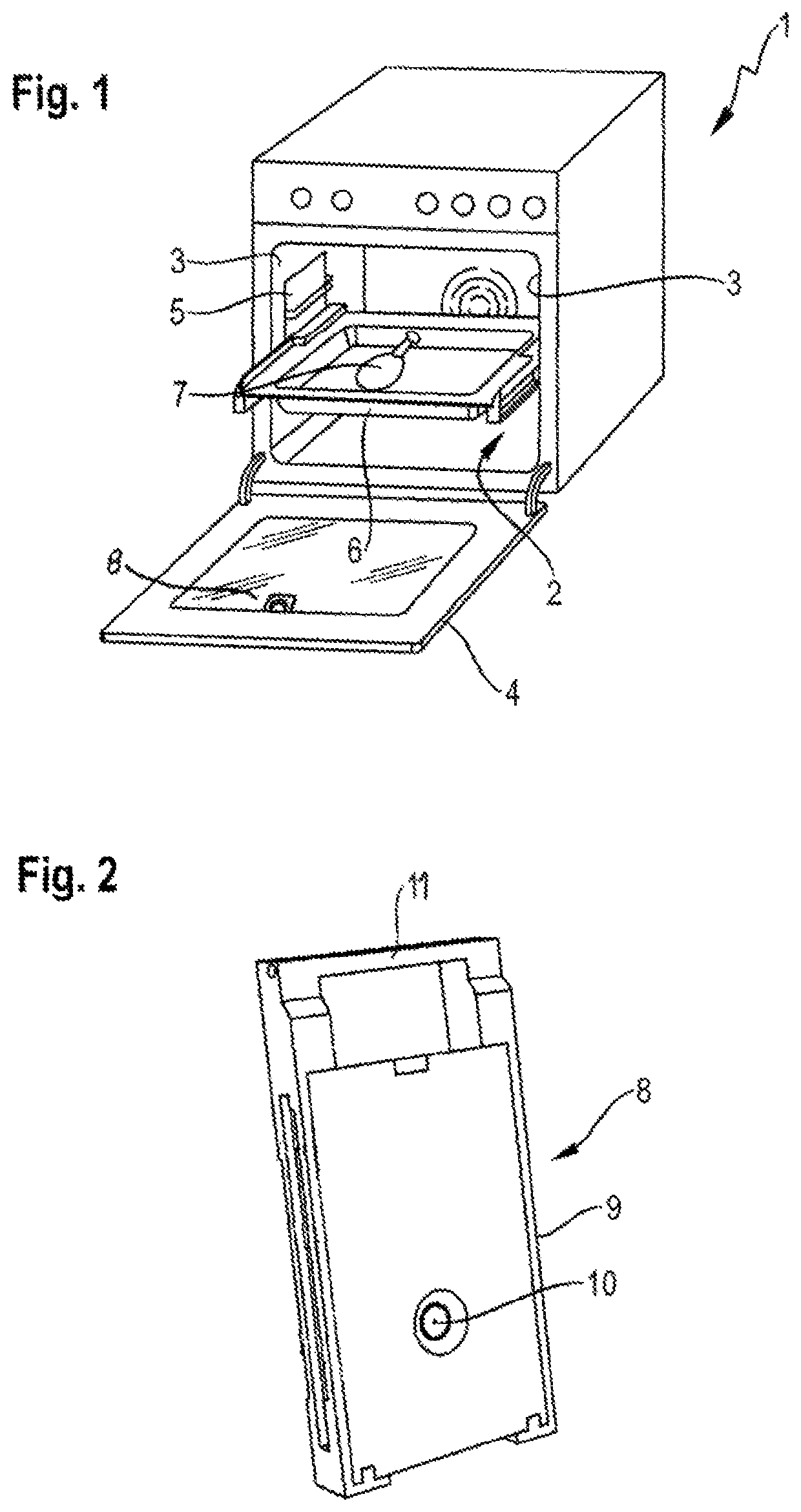
[0028]FIG. 1 shows a perspective representation of a cooking appliance 1 for preparing foodstuffs, which, in the exemplary embodiment, is a baking oven. The cooking appliance 1 includes a cooking compartment 2, which is delimited by side walls 3 of the oven. At its front, the cooking compartment 2 has a loading opening, which can be closed by a door 4. Situated on the side walls 3 are side rails 5, respectively, which are suitable for receiving carriers 6 for food to be cooked, such as e.g. racks or trays, on which the food 7 to be cooked rests. For identifying the properties of the food 7 to be cooked, a sensor module 8 is provided in the door 4. This installation position has proved to be particular effective, as it is closest to the usual viewing angle of the user into the cooking appliance 1 or at the food 7 to be cooked.

[0029]FIG. 2 shows a perspective representation of...


PUM


Abstract

A cooking appliance, in particular a baking oven, includes a cooking compartment for cooking food to be cooked, and a door for closing the cooking compartment in an operating position, with the door having a receptacle. Arranged in the door is a sensor module for identifying a property of the food to be cooked when the door assumes the operating position. The sensor module is receivable in the receptacle and reversibly removable from the receptacle.

Description

CROSS-REFERENCES TO RELATED APPLICATIONS[0001]This application is the U.S. National Stage of International Application No. PCT / EP2018 / 053269, filed Feb. 9, 2018, which designated the United States and has been published as International Publication No. WO 2018 / 153690 A1 and which claims the priority of German Patent Application, Serial No. 10 2017 202 778.9, filed Feb. 21, 2017, pursuant to 35 U.S.C. 119(a)-(d).BACKGROUND OF THE INVENTION[0002]The invention relates to a cooking appliance comprising a cooking compartment for cooking food to be cooked.[0003]A cooking appliance having a camera for observing the food to be cooked is known from the document DE102007048834A1. The disadvantage of this solution is that the camera is exposed to the high temperatures in the baking oven. Accordingly, the maximum temperature of the baking oven is substantially limited to the maximum temperature of the camera, so that operating modes demanded by the user, such as e.g. hot air at 300° C. for pizz...

Claims


Application Information

Patent Timeline
IPC IPC(8): F24C7/08F24C15/04
CPCF24C7/085F24C15/04
Inventor ERBE, SEBASTIANHIMMEL, ARNULFNEUMAYER, DAN
Owner BSH BOSCH & SIEMENS HAUSGERAETE GMBH
Why Eureka
Try Eureka