Automated road-rail transportation system with side stabilization

Active Publication Date: 2022-01-25
WILLIAMS THOMAS HOLTZMAN
View PDF39 Cites 0 Cited by
  • Summary
  • Abstract
  • Description
  • Claims
  • Application Information

AI Technical Summary

Benefits of technology

[0019]A track system comprised of tracks with two support rails and one or two side stabilizers. Side stabilizers may be exterior bars or recessed grooves. Vehicles have rail wheels that are supported and maintained over the support rails with lateral guidance from the side stabilizer. An interior side roller and a retractable exterior side roller contact a side stabilizer bar for guidance. A dual-flanged wheel inserted into a recessed groove is an alternate side stabilizer method for lateral guidance. At a decision point before a junction, vehicles change tracks by releasing the current side stabilizer and engaging the opposite side stabilize

Problems solved by technology

However, traveling on foot potentially relatively long distances from homes or businesses to and from rail terminals is a problem.
Disposing of a commuter vehicle after getting to the rail terminal is also a problem, as is procuring another commuter vehicle when getting off of the rail.
Bicycles are an efficient mode of transportation and can sometimes be c

Method used


Image

  • Automated road-rail transportation system with side stabilization
  • Automated road-rail transportation system with side stabilization
  • Automated road-rail transportation system with side stabilization

Examples


Example

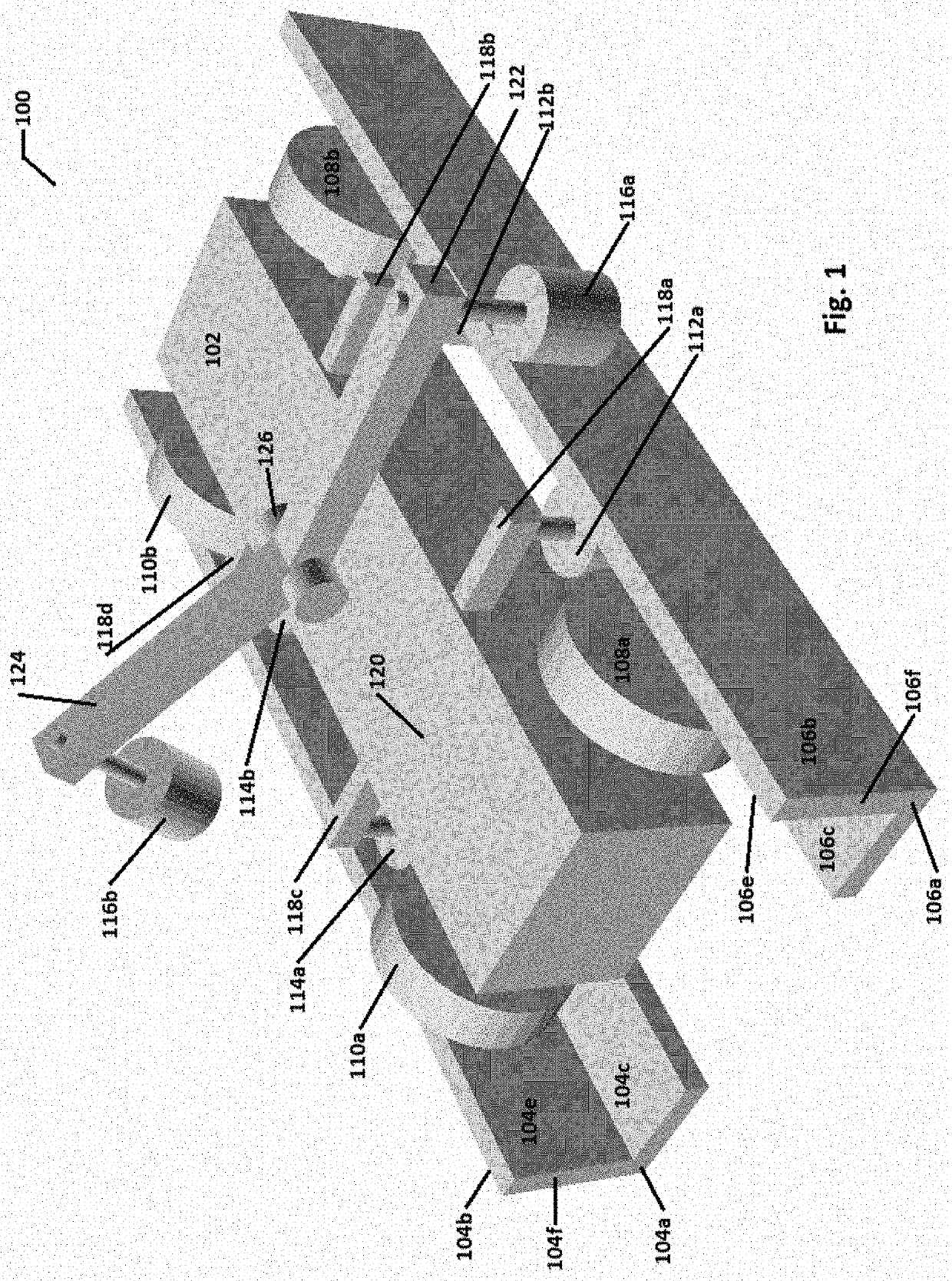
[0040]FIG. 1 is a perspective rendering 100 of a track system with a vehicle 102. Tracks are comprised of a left support rail 106a, a right support rail 104a, and one or two side stabilizer bars such as 104f and 106f, as well as a support structure (not illustrated). The vehicle 102 is rolling over the pair of rails, right rail 104a and left rail 106a. The terms left and right are referenced to the direction of vehicle travel, which is towards the bottom-left. Each rail has a stabilizer bar, such as right stabilizer bar 104f and left stabilizer bar stabilizer 106f, which in this drawing are vertical bars attached to the rails. The stabilizer bars are shown as integral parts of the rails but could alternately be attached with connecting brackets. Support rails have horizontal surfaces 104c and 106c. Side stabilizer bars 104f and 106f have an interior vertical surface 104e and 106e, and external vertical surfaces 104b and 106b. Four rail wheels 108a, 108b, 110a and 110b support the ve...


PUM


Abstract

A track system for transporting people and goods with two support rails plus a side stabilizer mechanism associated with one or both rails. The side stabilizer is employed to provide lateral stability and keep a vehicle's rail wheels on the support rails. The side stabilizer may be a protruding bar or a recessed groove. This track system enables vehicles to change support rails at a junction with stationary non-switching rails. Rail wheels roll over the support rails and support the weight of the vehicle while on the rails. Interior side rollers contact the interior of the bar side stabilizer and maintain the vehicle's rail wheels centered over the support rails. Exterior side rollers contact an exterior of one of the bar side stabilizers and forces the vehicle to stay on the current track or to change to a different track. Recessed grooves and dual-flange wheels can alternately provide side stabilization. At track junctions the vehicle can change direction, pass other vehicles, change lanes, turn-around, and load or unloading passengers or freight. This track system may be integrated with a conventional road system or with a controlled-access (autobahn/interstate) highway system. Optional road wheels allow the vehicle to exit the track system and travel on conventional roads, or dual-mode road/rail wheels can be used for travel on both track and pavement. An automatic traffic control system controls traffic on the track system and enables self-driving vehicles. Powering for the vehicles can be provided by the track system. The system can be miniaturized and used for the model/toy market.

Description

CROSS REFERENCE TO RELATED APPLICATIONS[0001]This application claims benefit and priority of US Provisional Patent Application Ser. No U.S. 62 / 918,544 filed Feb. 4, 2019 and US Non-Provisional Patent Application Ser. No U.S. Ser. No. 16 / 780,015 filed Feb. 3, 2020. The disclosures of this application are incorporated herein by reference in their entireties.FIELD[0002]This invention relates to rail systems in general, and to vehicles that can operate on both rails and roads, and to toy models derived from such systems.BACKGROUND[0003]There is currently a need for improved transportation worldwide, complicated by high population density and climate change from use of fossil fuels for transportation. Rails are an efficient method for transporting people and material due to low rolling resistance on rails, relative to roads. Rails can also have advantages of cheap construction and have an ability to power the vehicles from electricity flowing through rails. Rails are also an efficient us...

Claims


Application Information

Patent Timeline
IPC IPC(8): E01B25/28B61B15/00B60F1/04B60F1/00
CPCE01B25/28B60F1/005B60F1/04B61B15/00B60F2301/04B60F2301/10Y02T30/00
Inventor WILLIAMS, THOMAS HOLTZMAN
Owner WILLIAMS THOMAS HOLTZMAN
Why Eureka
Try Eureka