
System and method for compensation of reflection on a display device

a display device and compensation system technology, applied in image analysis, image enhancement, instruments, etc., can solve the problems of speculative reflection, further confusion of a person's view, and difficulty in viewing conten

Active Publication Date: 2022-02-15
FAURECIA IRYSTEC INC
View PDF7 Cites 1 Cited by
  • Summary
  • Abstract
  • Description
  • Claims
  • Application Information

AI Technical Summary

Benefits of technology

This approach effectively reduces the impact of specular reflections on the display, enhancing readability and user experience by digitally processing the target image to mitigate reflections perceived by the viewer, even in bright ambient environments.

Problems solved by technology

Modern display devices, especially those found on mobile devices, tend to show specular reflections in high-ambient lighting situations.
As seen in FIGS. 1A and 1B, such reflections make it difficult to view content, and the shifting highlights corresponding to background changes and screen tilting further confounds a person's view, particularly for video.
A commonly applied method to mitigate the effect of ambient involves raising the black level, but this only serves to further undermine contrast and does little to compensate for the confound between displayed content and reflected background information.
However, bright ambient environments pose a number of difficulties, including screen reflections, surrounding glare, and limited display brightness.
The unacceptable price in a mobile device is power consumption, but for automotive, it is mostly a question of technological limits.
While strides have been made in thin-film coatings for touch screens, and meta-materials hold promise for further improvements, screen reflections will never be eliminated completely when illumination sources are orders of magnitude brighter than the display.
The problem is simply too large to go away under all conditions.

Method used


Image

  • System and method for compensation of reflection on a display device
  • System and method for compensation of reflection on a display device
  • System and method for compensation of reflection on a display device

Examples


example implementation 1

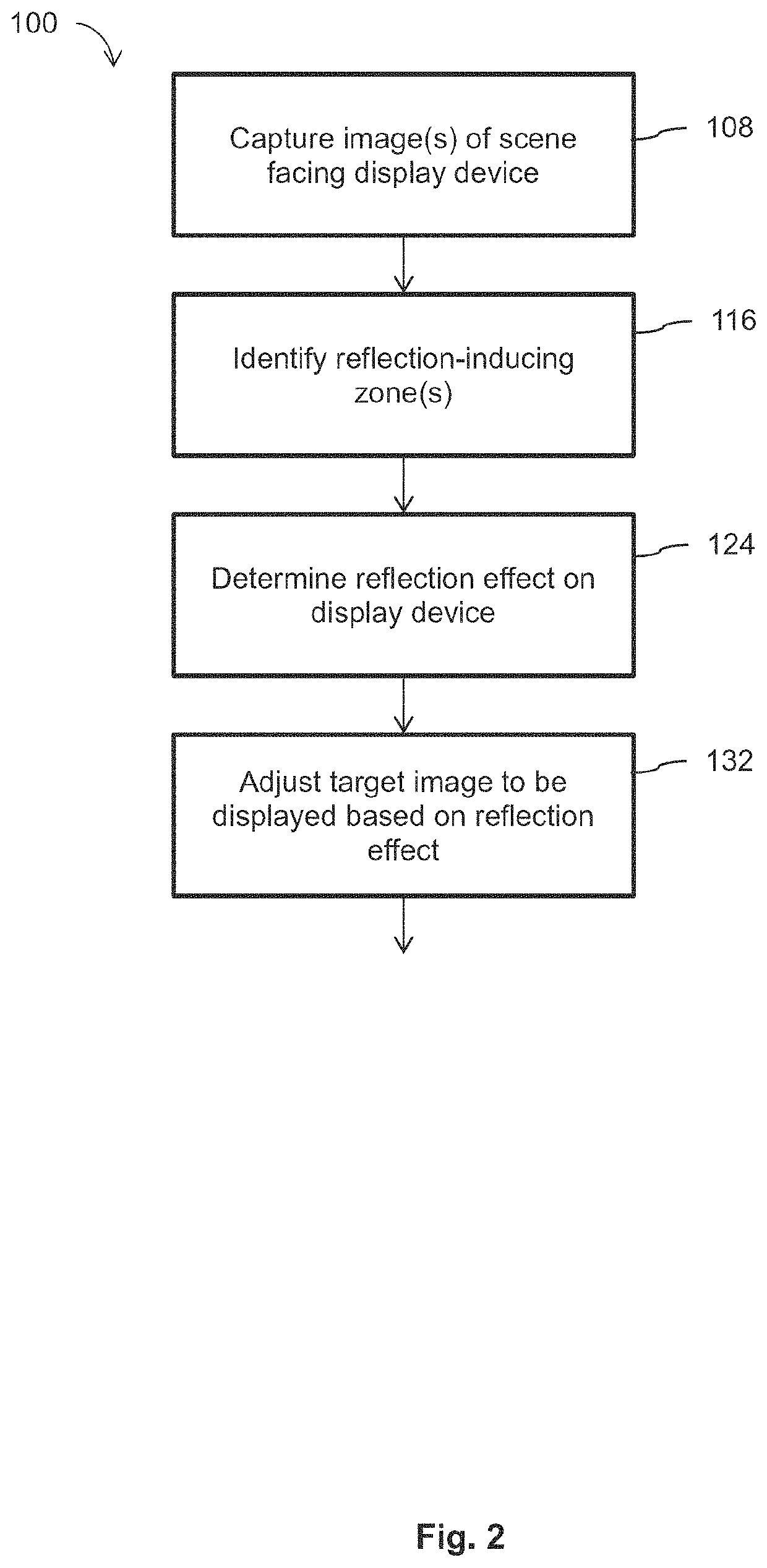
[0090]The basic concept is to take continuous video, ambient light and motion sensor data from a mobile device, and use it to deduce in real-time the current reflections seen by the user on his or her screen. The head position is simultaneously tracked in order to reproject the bright regions as seen by the front-facing camera.

[0091]The main challenge with veil subtraction lies in the accurate prediction of the reflection image as seen from the viewer's perspective. If the reflection image is in the wrong place, the results may be deteriorated due to subtracting the wrong veil, as shown in FIGS. 8a and 8b. Veil estimation requires (a) knowing where the viewer's eyes are located and (b) knowing the brightness and position of significant reflection sources are, both relative to the display.

[0092]In one example implementation, it is assumed that the device being used is equipped with a front-facing camera, an ambient light sensor, and motion sensors to provide when and how the display ...

example implementation 2

Creating a Demo for Automotive Display Applications

[0127]The automotive application is a constrained subproblem that avoids the need to estimate the distances to highlight boundaries in the scene, since the rough geometry of the vehicle is known. The viewer's head position still needs to be tracked based on front-camera data. For example, Android comes with built-in calls that perform this task.

[0128]The viewer's eye position together with the camera field of view and position with respect to the display area are used to reproject bright region locations to where they are expected to appear in the reflected screen. This step is performed on a pixel-by-pixel basis in over-threshold regions of the captured image, but at a reduced resolution to maintain responsiveness. In this situation, shifts in the viewer's head position and changes in the scene behind the viewer are responded to. Some delay (ex: on the order of fraction of seconds) is acceptable.

[0129]The example implementation see...

example implementation 3

Modifying Demo for Mobile Applications

Single-Viewer Head-Tracking

[0137]With input from orientation sensor and front-facing camera, track viewer's head based on likely / possible viewing configurations. Use head-size and / or eye spacing to estimate distance and associated silhouette boundary.

Digesting Motion-Sensor Input

[0138]Access motion-sensor and develop robust method for detecting “parallax shifts” in plane of display as needed for boundary distance determination. Learn to discriminate between in-plane shifts and the more common rotations that occur as a user holds the device naturally while interacting and viewing content. Use recorded front-facing video to evaluate performance of motion-tracking analysis.

Estimating Highlight Region Boundaries

[0139]Using thresholding technique, identify bright region boundaries and use perpendicular in-plane motion to estimate distances and connect contours as needed where distances are unreliable. Check against measurements.

Live Tracking

[0140]Use...


PUM


Abstract

A system and method for compensating for reflections caused by light-generating objects in the scene facing a display device includes capturing images of the scene. Reflection-inducting zones corresponding to the light generating objects are identified from the captured images. The reflection effect on the display device from the reflection-inducing zones are estimated. A target image to be displayed on the display device is adjusted based on the estimated reflection effect.

Description

RELATED PATENT APPLICATION[0001]The present application is a National Stage of International Application No. PCT / CA2017 / 051526 filed on Dec. 18, 2017, which claims priority from U.S. provisional patent application No. 62 / 436,667, filed Dec. 20, 2016 and entitled “SYSTEM AND METHOD FOR COMPENSATION OF REFLECTION ON A DISPLAY DEVICE”, the disclosure of which is hereby incorporated by reference in its entirety.TECHNICAL FIELD[0002]The technical field generally relates to performing digital image processing to compensate for the reflection of one or more specular reflections within an ambient environment.BACKGROUND[0003]When light interacts with the display device of a mobile device, the light may be reflected in multiple ways. For example, reflectance can be quantified in terms of diffuseness of reflection, varying between fully diffuse to fully specular. For example, shining a spot light on a perfect mirror will provide only specular reflection such that the spot light will only be vi...

Claims


Application Information

Patent Timeline
Patent Type & Authority Patents(United States)
IPC IPC(8): G09G5/10G06T7/514G06T7/70
CPCG09G5/10G06T7/514G06T7/70G06T2207/30201G09G2320/0686G09G2320/08G09G2354/00G09G2360/144G06T5/50G09G5/363G09G2320/066G09G2320/068G09G2380/10G06T7/55G06T5/94
Inventor WARD, GREG
Owner FAURECIA IRYSTEC INC
Features
  • Generate Ideas
  • Intellectual Property
  • Life Sciences
  • Materials
  • Tech Scout
  • Unparalleled Data Quality
  • Higher Quality Content
  • 60% Fewer Hallucinations
Learn More