
Transparent display device

a display device and transparent technology, applied in non-linear optics, instruments, optics, etc., can solve the problems of reducing the transparency of lcds and affecting the display effect, and achieve the effect of optimizing the visual experience, maximizing the transparency, and increasing the display

Active Publication Date: 2022-02-22
SHENZHEN CHINA STAR OPTOELECTRONICS SEMICON DISPLAY TECH CO LTD
View PDF16 Cites 0 Cited by
  • Summary
  • Abstract
  • Description
  • Claims
  • Application Information

AI Technical Summary

Benefits of technology

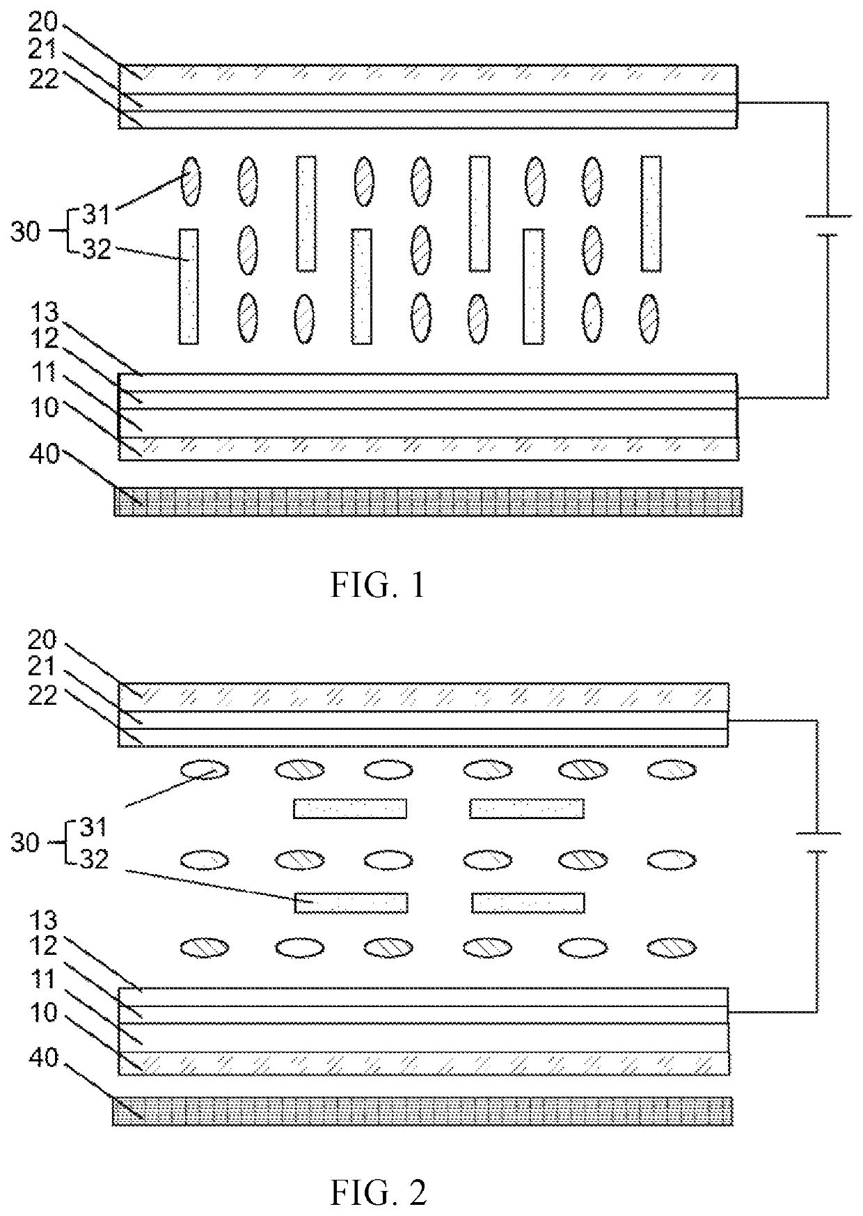
[0019]The beneficial effect is that after removing an upper polarizer, a lower polarizer, and a color filter that are disposed in the traditional display device, a normal display still can be realized by doping quantum rods in the liquid crystal layer, thereby realizing a higher transparent display effect. Specifically, an electric field is used to control the twist of liquid crystals to drive the twist of quantum rods, and an area receiving the irradiation from backlight varies with different twist levels of the quantum rods, that is, the intensity receiving the irradiation from the backlight will be various, which leads to different intensity of self-illumination, so a light and dark contrast is generated to realize displaying. Therefore, the transparent display device provided by the present invention has higher transparency and optimizes a visual experience of the transparent display device. Furthermore, because processes of the upper polarizer, the lower polarizer, and the color filter are omitted, process time and costs can be saved.

Problems solved by technology

The technical problem is that the existing transparent LCDs usually retain a color filter (CF) layer or add white pixels, and an upper polarizer and a lower polarizer are also retained for displaying colors.
Such a design inevitably reduces the transparency of the LCDs and affects their display effect.

Method used


Image

  • Transparent display device

Examples


Embodiment Construction

[0023]The following descriptions for the respective embodiments are specific embodiments capable of being implemented for illustrating the present disclosure with referring to the appending drawings. The spatially relative terms mentioned in the present invention, such as “upper”, “lower”, “front”, “back”, “left”, “right”, “inner”, “outer”, “lateral” are only directions with referring to the accompanying drawings. Therefore, the spatially relative terms used are merely for describing and understanding the present invention, it is not intended to limit the present invention. In the drawings, units with similar structure are represented by the same label.

[0024]The present invention provides a transparent display device, including a first transparent electrode layer 12, a second transparent electrode layer 21 disposed opposite to the first transparent electrode layer 12, and a liquid crystal mixture layer 30 disposed between the first transparent electrode layer 12 and the second trans...


PUM

PropertyMeasurementUnit
sizeaaaaaaaaaa
sizeaaaaaaaaaa
sizeaaaaaaaaaa

Abstract

A transparent display device includes a first transparent electrode layer, a second transparent electrode layer disposed opposite to the first transparent electrode layer, and a liquid crystal mixture layer disposed between the first transparent electrode layer and the second transparent electrode layer, wherein the liquid crystal mixture layer includes liquid crystal molecules and quantum rods.

Description

FIELD OF INVENTION[0001]The present invention relates to the field of display technology, and more particularly, to a transparent display device.BACKGROUND OF INVENTION[0002]With the rapid development of display field, various types of display devices have gradually crowded into the market. Among them, transparent display devices have received more and more attention because of their unique performance.[0003]Transparent liquid crystal displays (LCDs) can display additional information without affecting the visibility of objects behind the LCDs. They can be used in display windows in supermarkets or shops, perspective refrigerator doors, etc., and they can also be used to create transparent boxes, decorative glass-lamps and other creative equipment in many fields. Consumers can enjoy the convenience brought by this technological innovation.[0004]The technical problem is that the existing transparent LCDs usually retain a color filter (CF) layer or add white pixels, and an upper polar...

Claims


Application Information

Patent Timeline
Patent Type & Authority Patents(United States)
IPC IPC(8): G02F1/1343G02F1/1335G02F1/1337
CPCG02F1/13439G02F1/1337G02F1/133614G02F1/134309G02F1/133602G02F1/13306G02F1/133617G02F2202/36G02F2203/34G02F1/133565
Inventor HOU, JUN
Owner SHENZHEN CHINA STAR OPTOELECTRONICS SEMICON DISPLAY TECH CO LTD
Learn More