
System and method for detecting ground engaging tool float for an agricultural implement

a technology of agricultural implements and tools, applied in the field of agricultural implements, can solve problems such as unfavorable seedbeds

Active Publication Date: 2022-03-01
INC BLUE LEAF I
View PDF37 Cites 1 Cited by
  • Summary
  • Abstract
  • Description
  • Claims
  • Application Information

AI Technical Summary

Benefits of technology

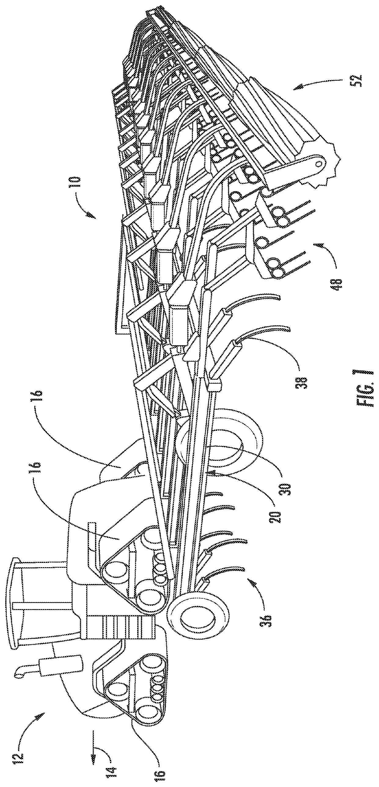
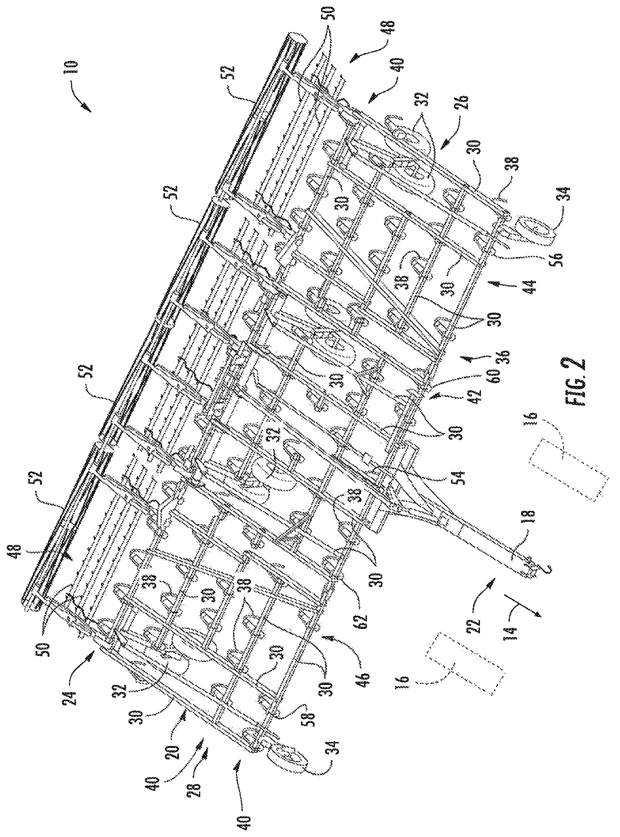
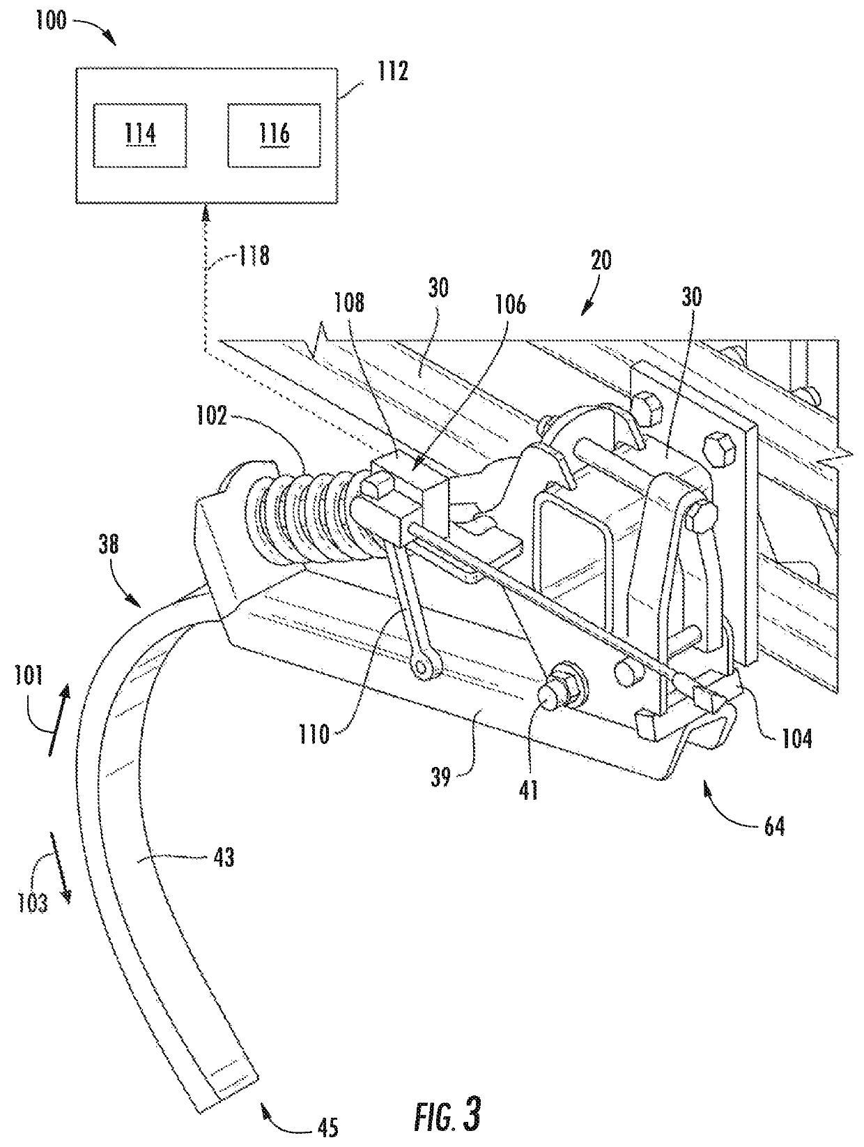
The present technology is about a system for detecting when a ground engaging tool (a tool that helps to prepare the ground for planting) of an agricultural implement is in a floating position during operation. This system includes a sensor that detects a certain parameter that indicates the position of the ground engaging tool relative to the frame of the implement. By monitoring this position, the system can identify when the ground engaging tool is displaced from its predetermined position for a certain period of time. This information can then be used to determine when a ground engaging tool float event is occurring during operation of the implement, which can help to improve the performance and efficiency of the agricultural implement.

Problems solved by technology

However, firm or compacted soil in certain portions of the field may exert a great enough force on the ground engaging tools to overcome the biasing force of the ground engaging tools.
Ground engaging tool float may result in an uneven seedbed.

Method used


Image

  • System and method for detecting ground engaging tool float for an agricultural implement
  • System and method for detecting ground engaging tool float for an agricultural implement
  • System and method for detecting ground engaging tool float for an agricultural implement

Examples


Embodiment Construction

[0021]Reference now will be made in detail to embodiments of the invention, one or more examples of which are illustrated in the drawings. Each example is provided by way of explanation of the invention, not limitation of the invention. In fact, it will be apparent to those skilled in the art that various modifications and variations can be made in the present invention without departing from the scope or spirit of the invention. For instance, features illustrated or described as part of one embodiment can be used with another embodiment to yield a still further embodiment. Thus, it is intended that the present invention covers such modifications and variations as come within the scope of the appended claims and their equivalents.

[0022]In general, the present subject matter is directed to systems and methods for monitoring the operation of one or more ground engaging tools of an agricultural implement. In several embodiments, the disclosed system and method may monitor the position ...


PUM


Abstract

In one aspect, a system for detecting ground engaging tool float for an agricultural implement may include an implement having a ground engaging tool pivotally coupled to a frame and a biasing element coupled between the frame and the ground engaging tool. The biasing element may be configured to bias the ground engaging tool to a predetermined ground engaging tool position relative to the frame. The system may also include a sensor configured to detect a parameter indicative of a current position of the ground engaging tool relative to the frame. Additionally, the system may include a controller configured to monitor the current position of the ground engaging tool based on measurement signals received from the sensor and identify a time period across which the ground engaging tool is displaced from the predetermined ground engaging tool position. The controller may be further configured to compare the identified time period to a threshold time period to determine when a ground engaging tool float event is occurring during operation of the implement.

Description

FIELD[0001]The present subject matter is generally directed to agricultural implements and, more particularly, to systems and methods for monitoring a current position of a ground engaging tool of an agricultural implement to allow ground engaging tool float events to be detected.BACKGROUND[0002]It is well known that, to attain the best agricultural performance from a field, a farmer must cultivate the soil, typically through a tillage operation. Modern farmers perform tillage operations by pulling a tillage implement behind an agricultural work vehicle, such as a tractor. Tillage implements typically include a plurality of ground engaging tools configured to penetrate the soil to a particular depth. In this respect, the ground engaging tools may be pivotally coupled to a frame of the tillage implement. Tillage implements may also include biasing elements, such as springs, configured to exert biasing forces on the ground engaging tools. This configuration may allow the ground engagi...

Claims


Application Information

Patent Timeline
Patent Type & Authority Patents(United States)
IPC IPC(8): A01B79/00A01B19/02A01B63/32A01B76/00A01B61/04G01D5/12G01D5/42A01B63/111A01B29/04A01B49/02
CPCA01B79/005A01B19/02A01B61/046A01B63/111A01B63/32A01B76/00G01D5/12G01D5/42A01B29/04A01B49/027Y02A40/22
Inventor KOVACH, MICHAEL G.BARRICK, CHRISTOPHERENDSLEY, JOHN C.HENRY, JAMES W.MEINERS, TRACEY D.PETERSON, KLINT J.
Owner INC BLUE LEAF I
Learn More