
External fixation for the correction of bone deformity and trauma

a bone deformity and external fixation technology, applied in the field of external bone fixation system for the treatment of bone deformity and trauma, can solve the problems of inconvenient movement, minimal or no weight bearing capacity, and uncomfortable current system for patients, so as to improve the patient's comfort and stability, facilitate the access to the limb, and stabilize the fixation point

Active Publication Date: 2022-03-08
NEW STANDARD DEVICE LLC
View PDF8 Cites 2 Cited by
  • Summary
  • Abstract
  • Description
  • Claims
  • Application Information

AI Technical Summary

Benefits of technology

The patent is about a technology that allows for the attachment of fixation plates to a patient's body using rods, posts, or telescoping struts. These plates can be customized for different patients and can be used to treat various medical conditions. The technology provides stability and strength to the patient's body while also allowing for easy access to the affected area. This can help improve the recovery process and make the treatment more effective.

Problems solved by technology

Current systems are both uncomfortable for the patient and inconvenient when a wound is cleaned.
In addition, current EBF systems for acute trauma may only provide a temporary fix until a definitive treatment is determined and they are unstable, difficult to move into a new position and have minimal or no weight bearing capability.

Method used


Image

  • External fixation for the correction of bone deformity and trauma
  • External fixation for the correction of bone deformity and trauma
  • External fixation for the correction of bone deformity and trauma

Examples


Embodiment Construction

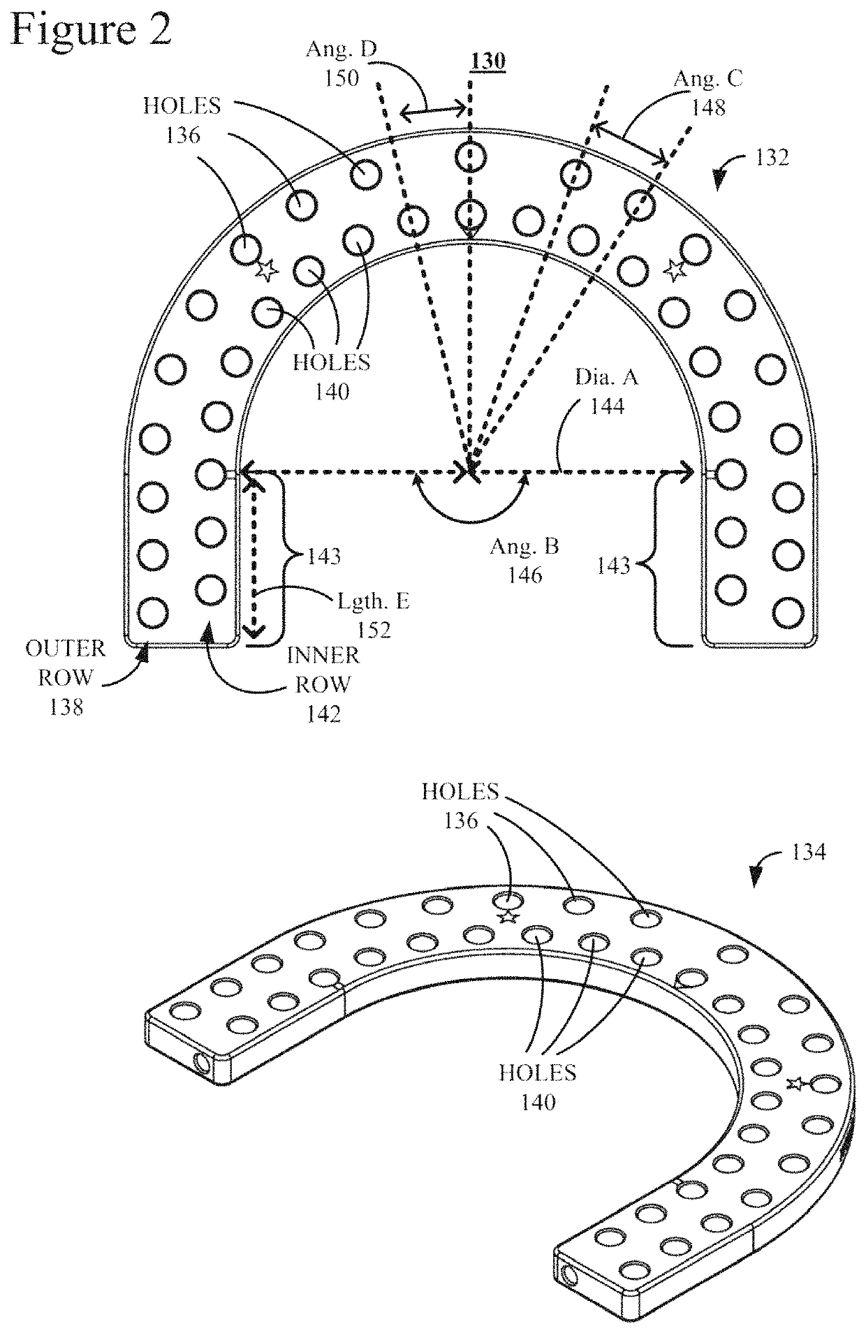
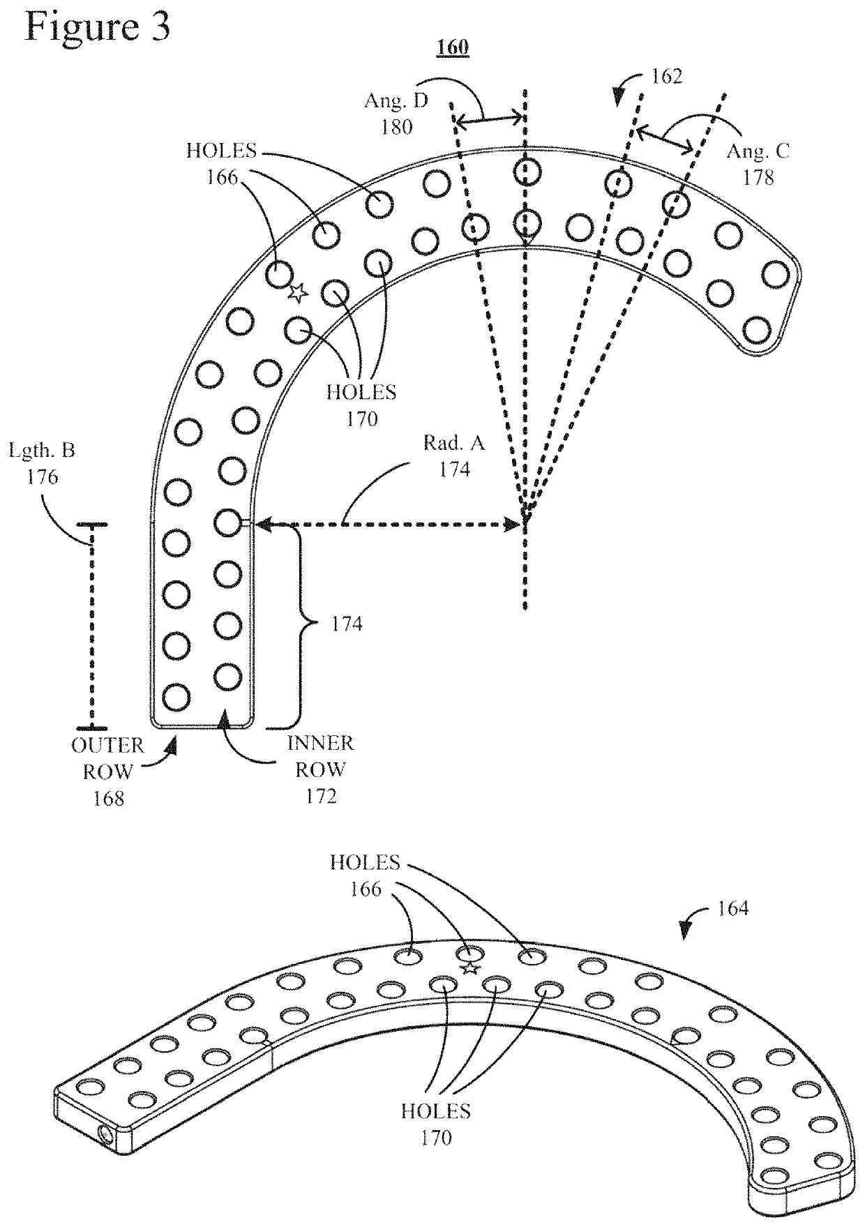
[0032]The illustrations and diagrams in the Figures illustrate the architecture, functionality, and operation of possible implementations of systems according to various embodiments of the present invention.

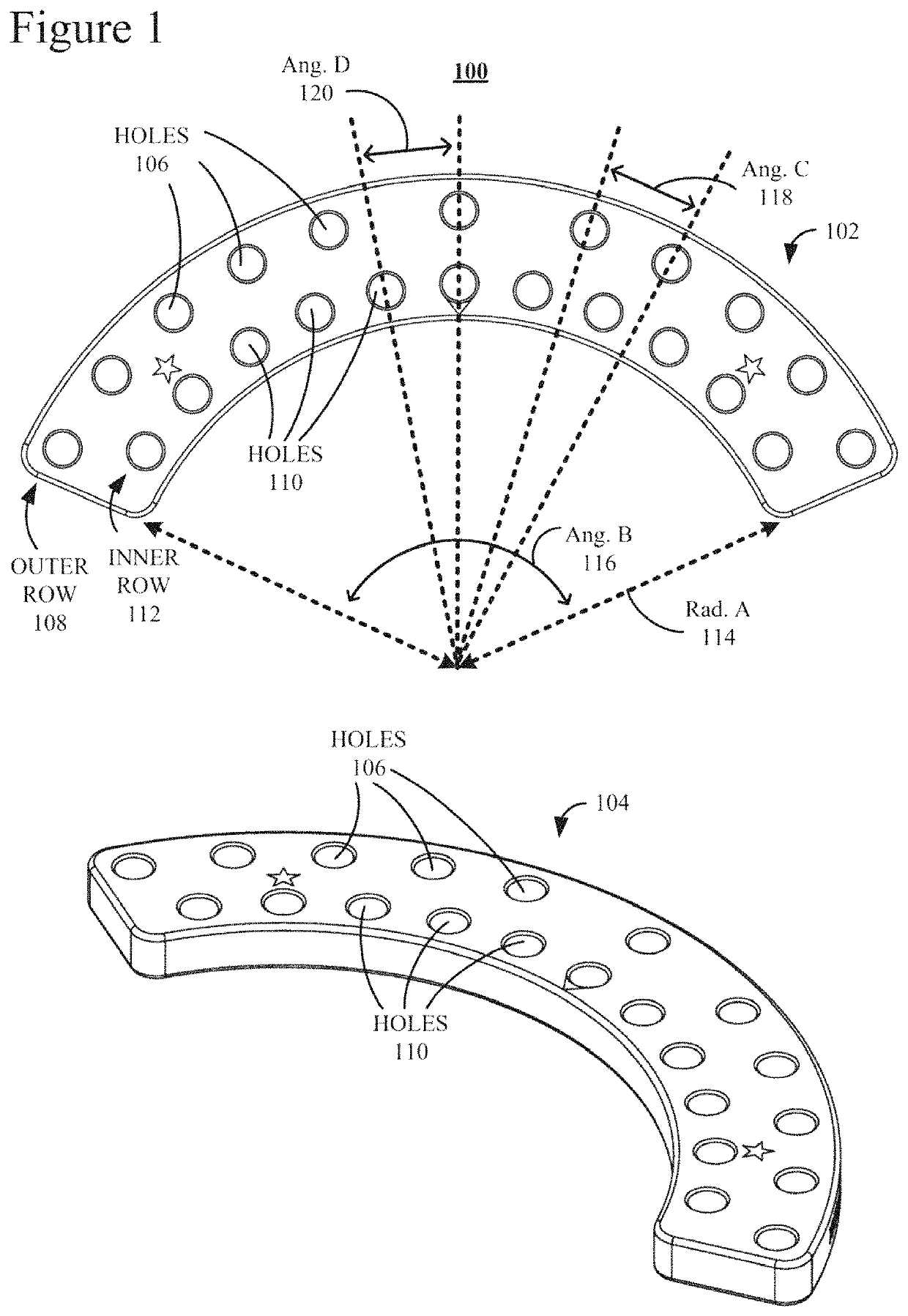
[0033]FIG. 1 is an illustration of two views of one embodiment of that which the Inventors have defined as a C Plate 100. C Plate 100 is illustrated from two (2) different angles, i.e., a top view 102 and a perspective view 104. C Plate 100 is typically employed to conform to a patient's extremity, or limb.

[0034]C Plate 100 has a semi-circular curvature that may follow the arc of a circle. C Plate 100 includes a row of holes 106, i.e. forming an outer row 108, and a row of holes 110, i.e., forming an inner row 112. For the sake of simplicity, only three holes in each of rows 108 and 112 are labeled. Rows 108 and 112 follow the curvature of C Plate 100. In this example, C Plate 100 covers an angle, or an Angle (Ang.) B 116, equal to approximately one hundred thirty-eight degrees (...


PUM


Abstract

Provided is an apparatus and component parts of a system for the external fixation of bones. The component parts include fixation plates such as a C-shaped Plate, an N-shaped Plate, a J-shaped Plate, a K-shaped Plate, an I-shaped Plate, a Foot Plate, a Z-shaped Plate and a T-shaped Plate. Two or more fixation plates are configured along an axis, the two or more fixation plates; a plurality of telescoping adjustable struts that connect a first fixation plate along the axis with a second fixation plate of the plurality of fixation plates along the axis, wherein the first and second fixation plates are adjacent plates along the axis; and a plurality of posts, each post connecting two adjacent fixation plates of the plurality of fixation plates along the axis.

Description

CROSS-REFERENCES TO RELATED APPLICATIONS[0001]The present application is a Continuation-in-part and claims the benefit of the filing date of an application entitled:[0002]“External Fixation for the Correction of Bone Deformity and Trauma,” Ser. No. 16 / 564,023, filed Sep. 9, 2019, assigned to the assignee of the present application, and herein incorporated by reference, which is a Continuation and claims the benefit of the filing date of an application entitled:[0003]“External Fixation for the Correction of Bone Deformity and Trauma,” Ser. No. 15 / 922,577, filed Mar. 15, 2018, now U.S. patent Ser. No. 10 / 413,328, issued Sep. 17, 2019, assigned to the assignee of the present application, and herein incorporated by reference.FIELD OF DISCLOSURE[0004]The claimed subject matter relates to an external bone fixation system for the treatment of bone deformity and trauma.BACKGROUND OF THE INVENTION[0005]Current External Bone Fixation (EBF) systems for the treatment of bone deformity and acute...

Claims


Application Information

Patent Timeline
Patent Type & Authority Patents(United States)
IPC IPC(8): A61B17/64A61B17/62A61B17/56A61B17/00
CPCA61B17/6433A61B17/62A61B2017/00477A61B2017/00991A61B2017/568A61B17/6425A61B17/645
Inventor WIGGINTON, ROBERT E.PHAMVU, BRYANT T.SHONEBARGER, ADAM P.HLAD, LEE M.KLEIN, JR., C. DOUGLAS
Owner NEW STANDARD DEVICE LLC
Learn More