Anchorage of continuous fiber-reinforced polymer strands

a technology of reinforced polymer strands and anchoring, which is applied in the direction of building components, structural elements, building material handling, etc., can solve the problems of high processing cost, increased processing time, and inability to meet the requirements of bending process from straight shaped cfrps, so as to reduce manufacturing costs, increase transport efficiency, and stable anchoring performance

Active Publication Date: 2022-03-08
TOKYO ROPE MFG +1
View PDF44 Cites 0 Cited by
  • Summary
  • Abstract
  • Description
  • Claims
  • Application Information

AI Technical Summary

Benefits of technology

[0019]According to the invention described in the claims, the untwisted diameter-expanded portion is formed by preliminarily untwisting the element wires, and filling and curing the curable materials in the clearance among the element wires in the untwisted section. Therefore, not only bonding force between the element wires and the concrete increases, but the bearing resistance from the concrete in the peripheral area newly increases due to an increased outside diameter in the untwisted diameter-expanded portion, thereby ensuring the anchoring force enough to resist the tensile force acting on the CFRP strands. With a conventional anchor reinforcing portion in a CFRP material, a material in a peripheral area where anchoring is possible has been limited to mortar or grout high in fluidity considering that the material of an anchoring object is surely filled among the element wires. That is, only the material in the peripheral area where anchoring is made is not limited to the mortar or the grout, and it is possible to provide a stable anchoring performance to an ordinary concrete material in which the coarse aggregate is mixed.
[0020]According to the invention described in the claims, the untwisted diameter-expanded portion is formed by preliminarily untwisting the element wires, and filling and curing the curable materials in the clearance among the element wires in the untwisted section. Therefore, when the CFRP strands are used as a tendon, an application method to anchor in the concrete as a fixing end portion anchorage and being prestressed, and an application method that provides the untwisted diameter-expanded portion in the middle of the CFRP strands and causes the untwisted diameter-expanded portion to function as a stressed end anchorage after prestressing.
[0021]According to the invention described in the claims, the untwisted diameter-expanded portion is formed by preliminarily untwisting the element wires, and filling and curing the curable materials in the clearance among the element wires in the untwisted section. Therefore, the anchorage according to the invention described in the claims is applicable as the fixing end portion anchorage or as the stressing end anchorage in a post-tension method. Furthermore, in both of these usages, the anchorage is anchored inside the concrete structure, and therefore, rust prevention measures and counterterrorism measures are not necessary due to no contact between the anchorage and an outside. Meanwhile, with a conventional anchoring end portion of steel PC strands and CFRP strands, an anchoring device is projected outward of the anchoring end portion in a case of a combination of an anchor plate and wedge anchoring or a case of the anchor plate and an expansion material sleeve anchoring. Therefore, the rust prevention measures, such as an oil seal inside the anchoring device, are necessary, and for the counterterrorism measures, there is no specific measures at present.
[0022]According to the invention described in the claims, it is not necessary to have a member corresponding to the metal sleeve or perform a heating process by fitting the CFRP strands in a mold to bend the CFRP strands in a plant or the like as with a conventional anchorage. Therefore, the anchorage can be manufactured even at a construction site, thereby ensuring a reduced manufacturing cost. Moreover, since it is not necessary to have the member corresponding to the metal sleeve, the CFRP strands can be transported in a rolled shape, thereby increasing transport efficiency, thus ensuring a lowered transportation cost.
[0023]Moreover, according to the invention described in the claims, since the untwisted diameter-expanded portion can be formed in any sections of the CFRP strands, an anchoring position is not limited to the end portion of the CFRP strands, thereby improving a freedom of design.
[0024]In particular, according to the invention described in claim 2, since the untwisted diameter-expanded portion has the front and the rear bundled so as not to be untwisted any further, a shape management of the untwisted diameter-expanded portion can be accurately performed, and a filling operation of the curable materials is smoothly performed to ensure improving the operation efficiency.

Problems solved by technology

In contrast to this, when a CFRP is used as a reinforcing material in place of the rebar, one problem is that performing a bending process from the straight shaped CFRP requires a significant labor.
That is, in order to perform the bending process from the straight shaped CFRP material, there has been a problem that, it is necessary to perform a heating process by fitting the straight shaped CFRP material before the heating process into a hook shaped molding die using dedicated processing equipment in a manufacturing plant.
Therefore, additional processing time was required and the processing cost was also extremely expensive.
However, in this case, in order to make use of an advantage of CFRP material that is corrosion free, it has been necessary to use an expensive and high performing stainless-steel sleeve, which is considerably excellent in corrosion resistance.
In view of this, there has been a problem of cost increase.
Moreover, since the element strands composed of CFRP material are low in both shear strength and shear rigidity, there has been a possibility of breakage by clamping forces from a lateral direction caused by, for example, the metal sleeve and expansion pressure.
Therefore, there has been a problem that, for example, the production of the anchoring tools using the metal sleeve is limited in some factories because of the stable quality management.
However, when CFRP material is used as a tendon instead of the steel PC strands of the crimping anchoring device described in JP-A-2004-183325, there existed the following problem.
Therefore, it is impossible to apply the crimping anchoring device described in JP-A-2004-183325 to CFRP tendons.
However, as described above, in order to make use of an advantage of the CFRP material that is corrosion free, it has been necessary to use an expensive and high performing stainless-steel material considerably high in corrosion resistance as a material of the sleeve, and therefore, there has been a problem of causing a cost increase.
Moreover, in order to reduce a breakage in association with the shear failure and the shear deformation of the element wires themselves formed of the continuous fibers, it is necessary to increase a diameter and a length of the sleeve, and therefore, there has also been a problem that it is difficult to achieve a downsized anchorage by shortening an anchoring length.
However, a study by the applicants has newly confirmed a problem that an anchoring effect fails to function, in order to anchor the CFRP strands in concrete in which ordinary coarse aggregate is mixed, not in the mortar, because with the method described in JP-A-2017-115485, the concrete is never completely filled within the clearance of the anchor reinforcing portion 3c, and thus, an expected anchoring force cannot be provided.
Therefore, when a tensile force corresponding to prestressing force is applied to both ends of the anchor reinforcing portion 3c as described in JP-A-2017-115485, the anchor reinforcing portion 3c disappears, and thus, there lies a problem of failing to obtain a function as an anchorage even though the cement-based filler 5 is filled after being tensioned.

Method used


Image

  • Anchorage of continuous fiber-reinforced polymer strands
  • Anchorage of continuous fiber-reinforced polymer strands
  • Anchorage of continuous fiber-reinforced polymer strands

Examples


verification experiments

[0061]Next, using Table 1, Table 2, and FIG. 7, verification experiments that have been performed to confirm an anchoring effect of the present invention will be described.

experiment 1

Pull-Out Experiment 1

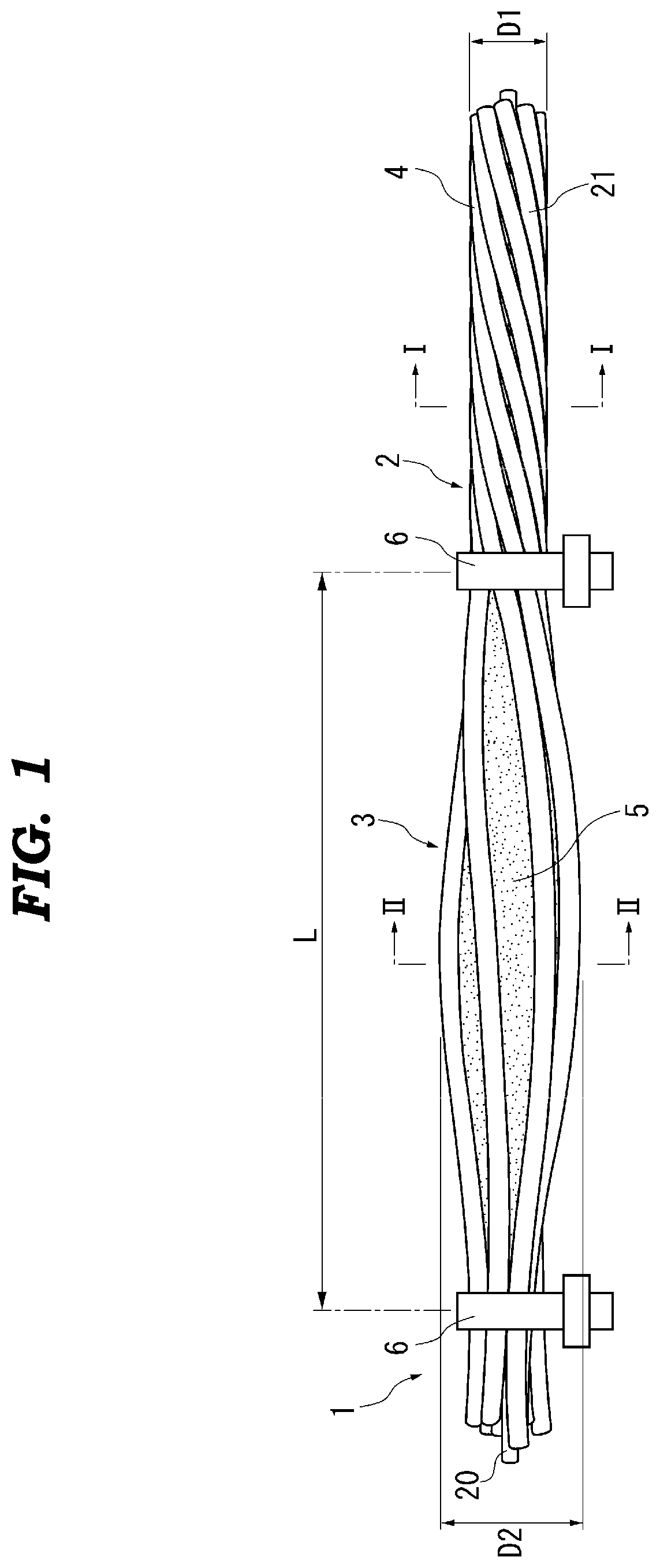
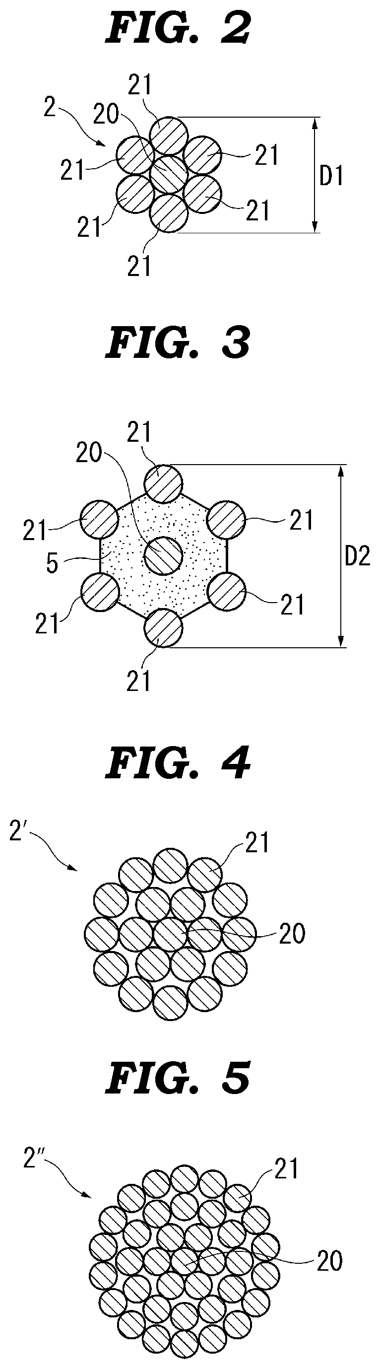
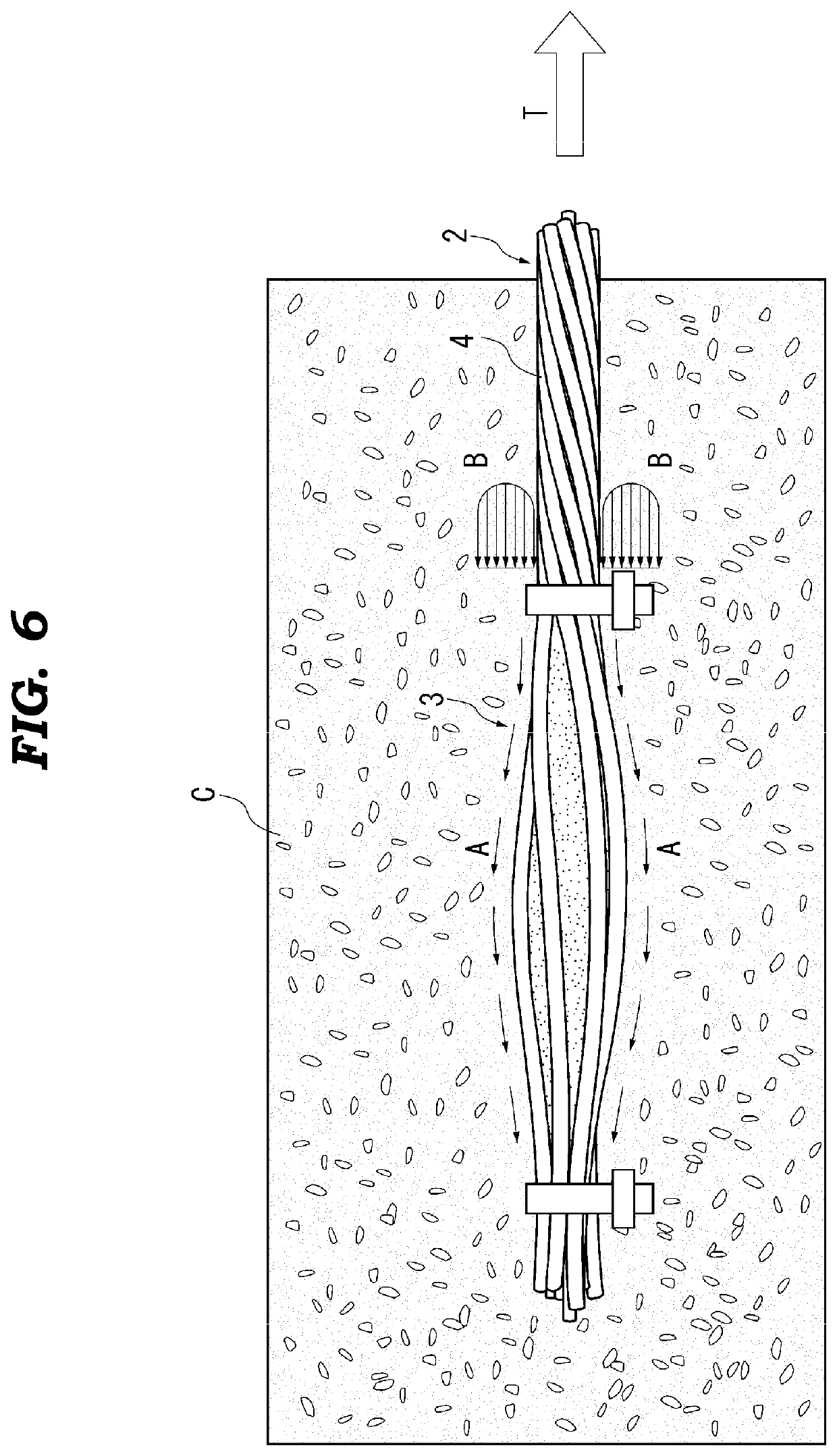
[0062]First, a pull-out experiment 1 in which CFRP strands are pulled out from test pieces in which the CFRP strands composed of the carbon fibers similar to the above-described anchorage 1 are anchored in concrete was executed. In this pull-out experiment 1, CFRP strands (guaranteed breaking load Pg=270 kN) with the diameter D1=15.2 mm formed of seven element wires similar to the above-described anchorage 1 was used. The maximum diameters D2 of the untwisted diameter-expanded portions 3 were 1.2 to 2.6 times the diameter D1 of the general portions 4. The test pieces have a concrete portion whose cross-sectional dimension was 500 mm×500 mm and whose length was 470 mm. Relatively high strength concrete with compressive strength of 56 N / mm2 was used. For a portion of the CFRP strands other than the untwisted diameter-expanded portion 3, the bond stress was cut with a vinyl tape+application of grease. Grout cement mortar with compressive strength of 70 N / mm2 was us...

experiment 2

Pull-Out Experiment 2

[0067]In a pull-out experiment 2, the comparisons of pull-out experiments were performed for a case where the curable material 5 (polymer cement mortar, compressive strength=74 N / mm2) filled into the untwisted diameter-expanded portion 3 was filled and a case where the curable material 5 was not filled, and the influences on the anchoring effect of the curable materials 5 were examined. The used CFRP strands have a diameter D1=15.2 mm (guaranteed breaking load Pg=270 kN). The concrete test piece has a cross-sectional dimension of 150 mm×150 mm, is provided with a 20 mm bonding cut, and has concrete compressive strength of 71 N / mm2.

[0068]The maximum diameter D2 of the untwisted diameter-expanded portion 3 was 1.5 times the diameter D1 of the general portion 4. For CFRP strands of test pieces, three types of test pieces with lengths L of the untwisted diameter-expanded portions 3 of ten times (L=152 mm), fifteen times (L=228 mm), and twenty times (L=304 mm) the di...


PUM

PropertyMeasurementUnit
diameteraaaaaaaaaa
diameteraaaaaaaaaa
tensile strengthaaaaaaaaaa

Abstract

In an anchorage (1) of continuous fiber-reinforced polymer (CFRP) strands that anchors continuous fiber-reinforced polymer strands (2) to concrete structures, there is provided an untwisted diameter-expanded portion (3) expanded to a diameter D2 by being radially expanded with respect to a diameter D1 of a general portion (4) of the CFRP strands (2) by untwisting any section of the CFRP strands (2) formed by stranding a plurality of element wires (20, 21) that are bundles of multiple continuous fibers, and filling and curing a time curable material (5) in a clearance among the element wires the untwisted section that is untwisted.

Description

CROSS REFERENCE TO RELATED APPLICATIONS[0001]This U.S. National Stage patent application claims the benefit of PCT International Patent Application Serial No. PCT / JP2018 / 026214 filed Jul. 11, 2018 entitled “Attachment Fitting For Continuous Fiber Reinforced Stranded Wire” which claims the benefit of JP Patent Application No. 2017-147677 filed Jul. 31, 2017 and JP Patent Application No. 2018-116652 filed Jun. 20, 2018, the entire disclosures of the applications being considered part of the disclosure of this application and hereby incorporated by reference.TECHNICAL FIELD[0002]The present invention relates to an anchorage of continuous fiber-reinforced polymer strands that anchors the continuous fiber-reinforced polymer (CFRP) strands composed of multiple continuous fibers to concrete structures.BACKGROUND ART[0003]Conventionally, there has been known, roughly divided, two methods as a technique to anchor a rebar to a reinforced concrete structure or a technique to anchor a tendon to...

Claims


Application Information

Patent Timeline
Patent Type & Authority Patents(United States)
IPC IPC(8): E04C5/12E04C5/08
CPCE04C5/125E04C5/085E04C5/127E04G21/12E04C5/073
Inventor MASUYA, HIROSHITANAKA, YOSHIHIROTANAKA, TORUKODA, EIJIWATASE, HIROSHITSUNOMOTO, MEGURU
Owner TOKYO ROPE MFG
Why Eureka
Try Eureka