Eureka AIR delivers breakthrough ideas for toughest innovation challenges, trusted by R&D personnel around the world.

Anchor clamping piece

A technology of clips and anchors, applied in structural elements, building components, building reinforcements, etc., can solve the disadvantage of clip follow-up and elastic deformation, reduce the occlusal force between clips and steel strands, and clip sliding wire, etc. problem, to improve the anchoring performance, increase the number of teeth, and prevent the clip from being bitten tightly.

Inactive Publication Date: 2011-04-06
天津市银燕预应力有限公司
View PDF0 Cites 0 Cited by
  • Summary
  • Abstract
  • Description
  • Claims
  • Application Information

AI Technical Summary

Problems solved by technology

However, at present, the ultimate strength of steel strands is generally increased, and some 1860-grade steel strands will reach more than 2000MPa, while the existing domestic clip-type anchorage is designed according to the bearing capacity calculated according to the standard ultimate strength of steel strands of 1860MPa. The 2.5-3mm cylindrical part of the head reduces the bite force between the clip and the steel strand; in addition, the positioning groove at the head of the clip is just in the taper hole of the anchor plate during the initial tension of the construction and the pre-tensioning stage of the static load test. The catchy mouth is very unfavorable to the follow-up and elastic deformation of the clip
These structural defects lead to the phenomenon of wire slipping and broken wires in the clips during actual use.

Method used


Image

  • Anchor clamping piece
  • Anchor clamping piece
  • Anchor clamping piece

Examples


Embodiment Construction

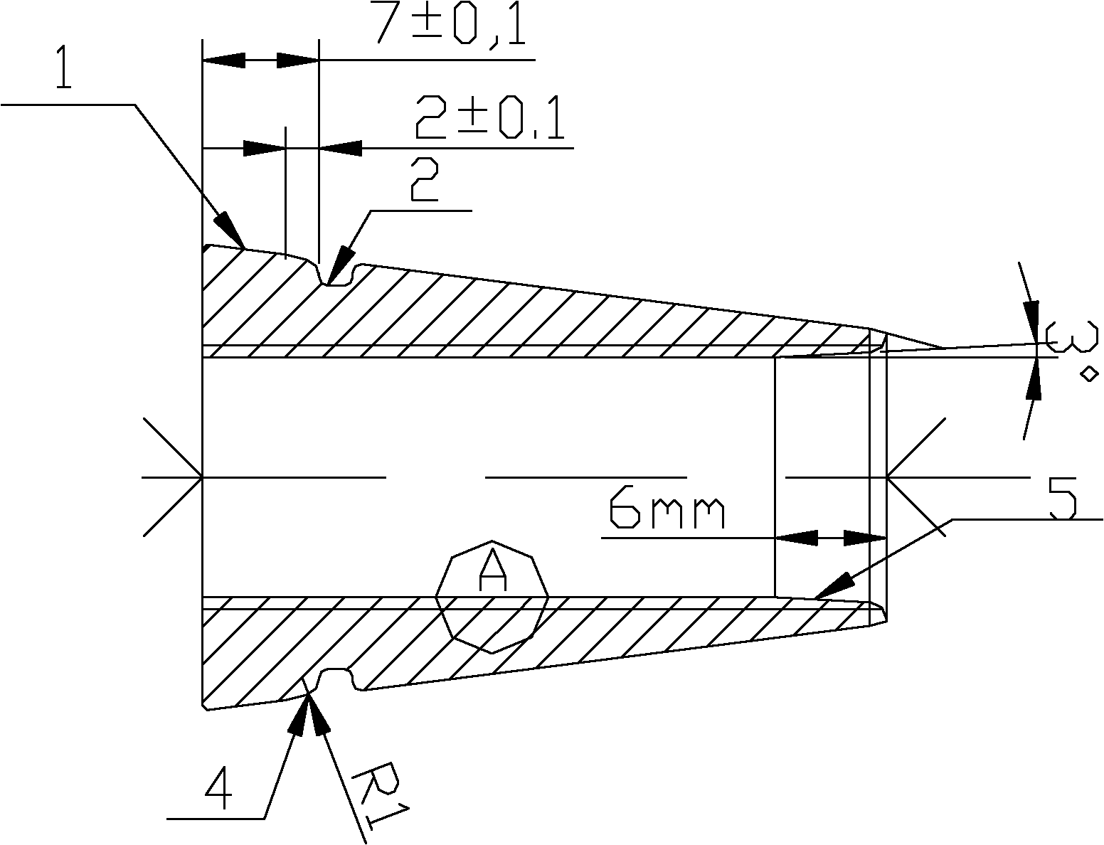
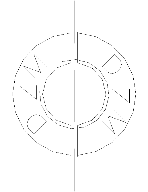
[0016] like figure 1 , 2 Shown: An anchor clip consisting of two clips. The small end surface to the large end surface of the clip is a conical surface 1, and the positioning groove 2 is located in the middle of the clip. Compared with the old clip, the positioning groove has moved down by 5mm. And both sides of the positioning groove are arc chamfered 4.

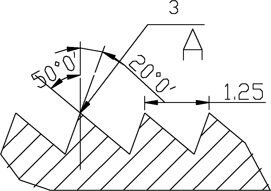
[0017] like image 3 Shown: the transition tooth 5 at the tail of the above-mentioned clip is a 3° arc chamfer, and the chamfer size is 6mm. The teeth 3 tooth shape of the clip is an inverted tooth shape, its tooth shape is 70°, and the tooth distance is 1.25mm (such as image 3 shown).

[0018] In this design, parameters such as the tooth profile angle and tooth pitch of the clip are selected reasonably, so as to ensure that the clip has sufficient bite force on the steel strand without excessive damage to the steel strand. It can effectively avoid the cracking, slipping and broken wires of anchor clips.


PUM


Abstract

The invention relates to an anchor clamping piece which comprises two clamping pieces. A circular conical surface is arranged between the small end surface and the large end surface of each clamping piece; a positioning groove is positioned in the middle of each clamping piece; and a tooth of each clamping piece is in an inverted tooth shape, and the tooth distance is 1.25mm. The invention has the advantage of simple structure, is convenient for use, can effectively prevent phenomena of fracture, sliding and breakage generated in the anchor clamping piece and has enough meshing force on a steel strand.

Description

Technical field: [0001] The invention belongs to a component in a prestressed anchoring system, in particular to an anchor clip. Background technique: [0002] Clips and anchors are the most critical components in the entire prestressed anchorage system. Through the wedge principle, the clip and the anchor plate cooperate with each other to clamp the prestressed steel strand and directly bear the tension of the prestressed structure. Its working principle is: after the tensioning and releasing of the anchorage starts, the jack slowly releases the pressure, the steel strand shrinks inwards, and drives the clamp to move; after the clamp is in place, the lateral clamping force on the steel strand gradually increases , the resistance of the clip wire teeth to prevent the shrinkage of the steel strand also increases. During this process, the clip slips relative to the tapered hole of the anchor ring to a certain distance and then is self-locked. As the jack continues to be str...

Claims


Application Information

Patent Timeline
IPC IPC(8): E04C5/12
Inventor 张军
Owner 天津市银燕预应力有限公司
Why Eureka
Eureka Blog
Learn More