Gas turbine engine induction system, corresponding induction heater and method for inductively heating a component

a gas turbine engine and induction system technology, applied in the field of turbine engines, can solve the problems of thermal stress in large gas turbine engine components, material weaknesses and potential damage, and the speed of gas or steam turbine engines starting or responding to changes in load demand, so as to reduce thermal difference, reduce thermal difference, reduce thermal difference

Active Publication Date: 2022-03-08
SIEMENS ENERGY GLOBAL GMBH & CO KG
View PDF6 Cites 0 Cited by
  • Summary
  • Abstract
  • Description
  • Claims
  • Application Information

AI Technical Summary

Benefits of technology

[0006]An aspect of the present disclosure may be a system for inductively heating a component of a gas turbine engine. The gas turbine engine may comprise a gas turbine engine induction system for inductively heating a component of a gas turbine engine comprising: an induction heater located proximate to a static component of the gas turbine engine; and wherein the induction heater is adapted to heat the static component prior to ignition and during transient conditions so as to reduce a thermal difference between the static component and at least one other component of the gas turbine engine.
[0007]Another aspect of the present disclosure may be an induction heater for a gas turbine engine. The induction heater may have a coil adapted to surround a static component of the gas turbine engine; and an electric component for transmitting electricity through the coil surrounding the static component, the transmission of electricity heats the static component so as to heat the static component prior to ignition and during transient conditions so as to reduce a thermal difference between the static component and at least one other component of the gas turbine engine.
[0008]Still yet another aspect of the present invention may be a method for inductively heating a component of a gas turbine engine. The method may comprise inductively heating a component of a gas turbine engine comprising: inductively heating a static component prior to ignition of the gas turbine engine and during a transient condition; and reducing a thermal difference between the static component and at least one other component of the gas turbine engine through the inductive heating of the static component.

Problems solved by technology

One of the limitations to how fast a gas or steam turbine engine can start or respond to changes in load demand are the thermal stresses in large gas turbine engine components, such as casings.
The thermal gradients within these components create thermal stresses, which if not effectively managed can result in material weaknesses and potential damage.
These limits can impact the performance of the gas turbine engine.
However, this can require constant heat application and are relatively slow.

Method used


Image

  • Gas turbine engine induction system, corresponding induction heater and method for inductively heating a component
  • Gas turbine engine induction system, corresponding induction heater and method for inductively heating a component
  • Gas turbine engine induction system, corresponding induction heater and method for inductively heating a component

Examples


Embodiment Construction

[0013]To facilitate an understanding of embodiments, principles, and features of the present disclosure, they are disclosed hereinafter with reference to implementation in illustrative embodiments. Embodiments of the present disclosure, however, are not limited to use in the described systems or methods and may be utilized in other systems and methods as will be understood by those skilled in the art.

[0014]The components described hereinafter as making up the various embodiments are intended to be illustrative and not restrictive. Many suitable components that would perform the same or a similar function as the components described herein are intended to be embraced within the scope of embodiments of the present disclosure.

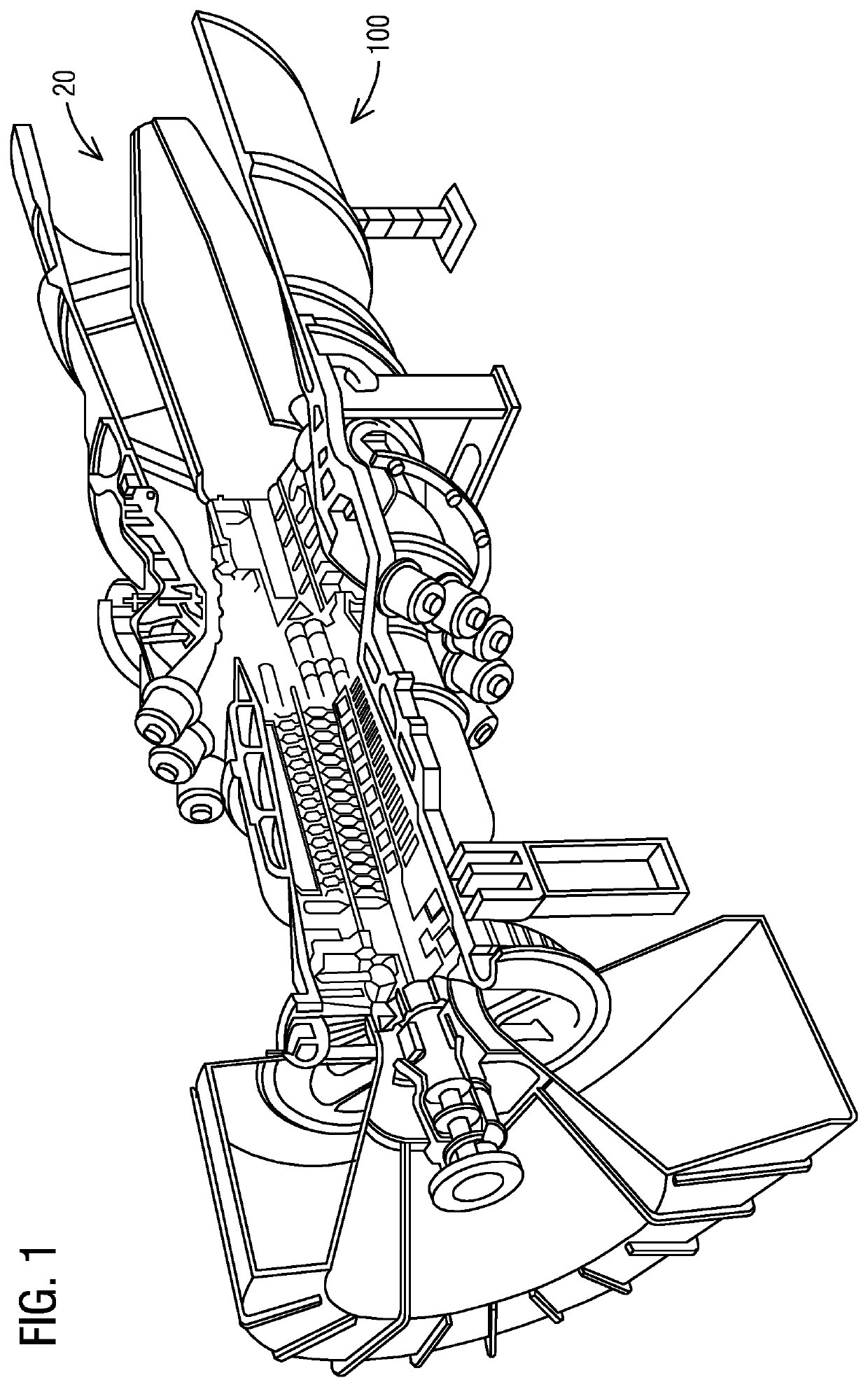
[0015]FIG. 1 shows a gas turbine engine 100. The gas turbine engine 100 has static component 20. In the example shown in FIG. 1, the static component 20 is a casing.

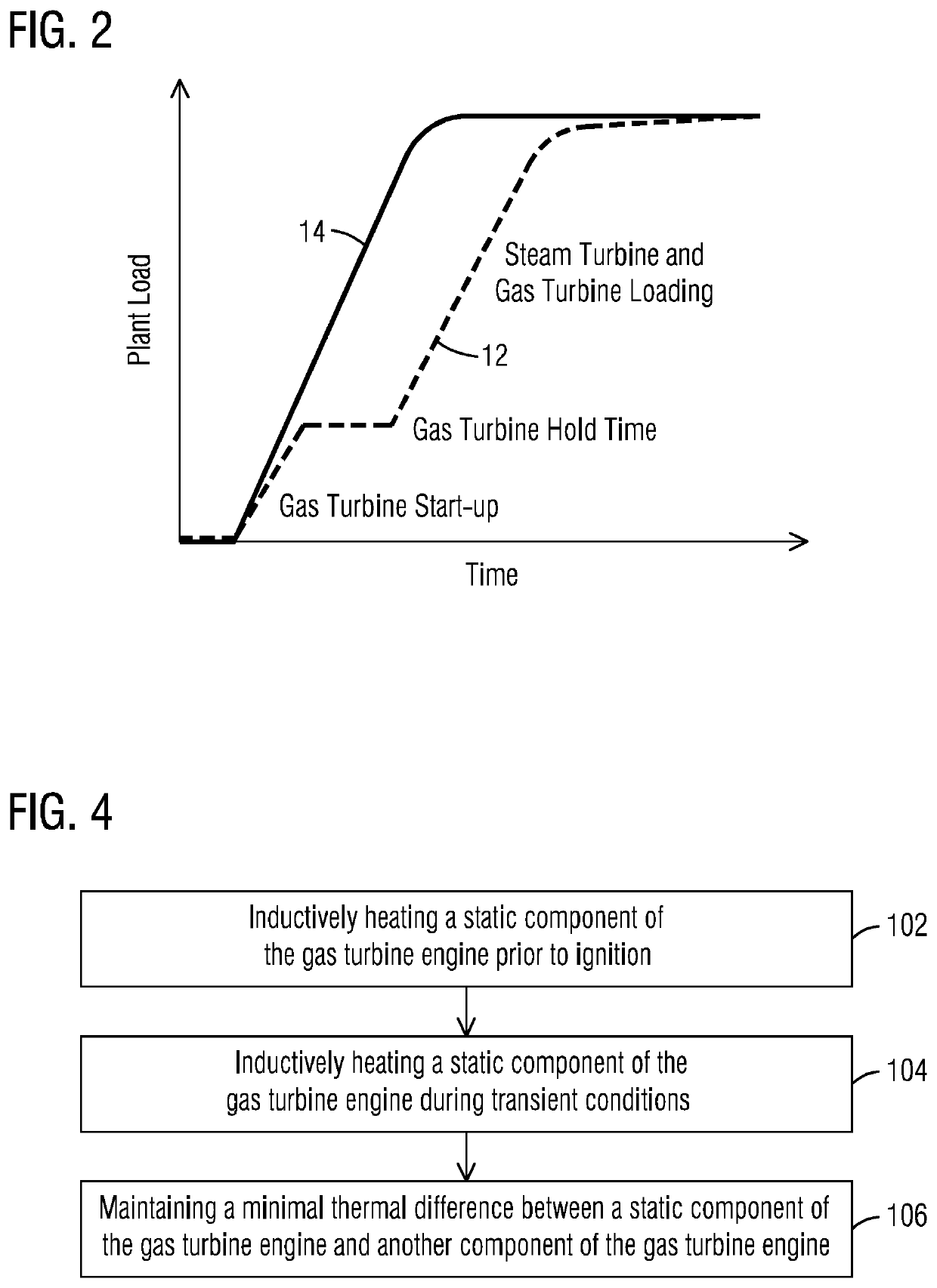
[0016]FIG. 2 is a graph illustrating the performance of the gas turbine engine 100 when the static ...


PUM


Abstract

An induction heater is employed with a gas turbine engine in order to heat a static component of the gas turbine engine. The heating of the static component is performed prior to the ignition of the gas turbine engine and during transient conditions. This minimizes thermal differences between the components of the gas turbine engine during transient conditions to thereby increase the life span of the components.

Description

BACKGROUND1. Field[0001]Disclosed embodiments are generally related to turbine engines, and in particular to applying induction heating to engine components during start up.2. Description of the Related Art[0002]The increased use of low cost renewable power generation has created a growth market for gas turbine engines as back-up or make-up power solutions. One of the limitations to how fast a gas or steam turbine engine can start or respond to changes in load demand are the thermal stresses in large gas turbine engine components, such as casings. As the gas turbine engine starts, internal surfaces are heated. The components closer to the gas path or with lower thermal inertia, such as thin casings or struts will heat faster than bulky outer casings. The thermal gradients within these components create thermal stresses, which if not effectively managed can result in material weaknesses and potential damage.[0003]In order to address these thermals differences, acceleration rate limit...

Claims


Application Information

Patent Timeline
Patent Type & Authority Patents(United States)
IPC IPC(8): F01D25/14F01D25/10
CPCF01D25/14F01D25/10F05D2220/32F05D2240/14F05D2260/20
Inventor CHOHAN, HARRYBOUFFARD, SÉBASTIENMALO, ALEXANDRESMITH, HAYDEN
Owner SIEMENS ENERGY GLOBAL GMBH & CO KG
Why Eureka
Try Eureka