
Sensor device with a selectively activatable display

a sensor device and activation technology, applied in the field of selective activation display, can solve the problems of pressure ulcers, tissue compression, and impairing blood flow to affected areas, and achieve the effect of convenient affixed to a patien

Active Publication Date: 2022-03-15
LEAF HEALTHCARE
View PDF196 Cites 0 Cited by
  • Summary
  • Abstract
  • Description
  • Claims
  • Application Information

AI Technical Summary

Benefits of technology

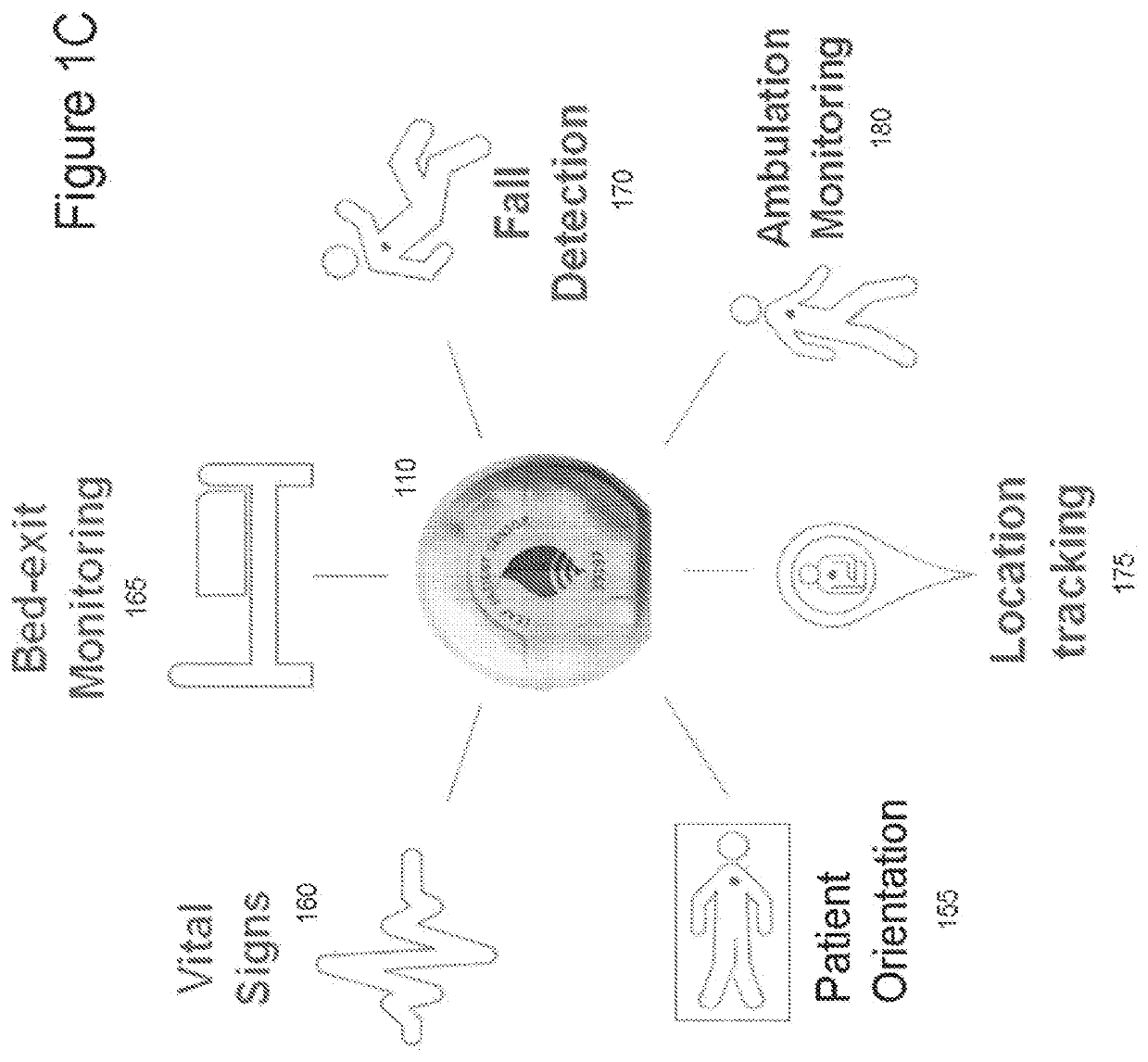
The present invention provides a lightweight, multi-function sensor that can be easily attached to a patient. This sensor includes a trio of sensors: accelerometer, magnetometer, and altimeter. It can detect patient movement, turns, and physical characteristics. The sensor can be a single-use, disposable device that is attached to the patient using a medical adhesive. The sensor can also track the direction the patient is facing, which can be useful in detecting bed exit attempts. By monitoring these characteristics, caregivers can have additional time to reach the patient before the bed exit occurs. The technical effects of this invention include improved patient safety and monitoring for caregivers.

Problems solved by technology

Pressure ulcers are a vast and growing problem in the United States and account for ˜$10 billion dollars in annual health care spending.
This unrelieved pressure causes compression of tissues and impairs blood flow to affected areas.
If the surface pressure is not relieved, the resulting shortage of blood flow can lead to localized tissue damage and cell death.
Pressure ulcers initially appear as areas of reddened skin, but can quickly develop into large open wounds if left untreated.
Pressure ulcers are a source of significant morbidity and mortality for patients.
In many healthcare facilities, such a turning schedule can be difficult to maintain.
Studies have shown that caregiver compliance with patient turning protocols is low and a high percentage of patients are not being turned appropriately.
Some explanations for this low compliance include difficulty monitoring patient position, ineffective turn reminders / alerts, and sub-optimal caregiver staffing ratios—all of which hinder efforts to prevent pressure ulcers.
To further exacerbate the problem, as the population ages, the percent of patients requiring turning is increasing, and yet there is a growing shortage of nursing staff, making it increasingly difficult to maintain compliance with prescribed turning schedules.
In addition, for patients with ambulatory challenges, bed exits and falls can present a serious risk of injury.
Such bed exits and falls can present significant care and liability issues for hospitals, assisted living institutions, hospices, and regular homes where a patient is being cared for.
Bed exits and falls have in the past proven particularly challenging to manage, because prompt detection has been difficult.
Monitoring systems for bed exits have proven unreliable, at least in part because such systems typically do not detect the preliminary movements that indicate a forthcoming exit by a patient who is likely to fall upon exiting the bed.
Likewise, systems for detecting falls have not had great success, in part because falls can occur slowly, and involve relatively short distances between the bed and either the floor or some intermediate object.
The costs associated with a fall can be enormous, including loss of life or serious injury for the patient.
From an economic standpoint, hospitals incur greatly increased costs in caring for patients injured due to a fall.
Moreover, such costs are typically not reimbursed by insurance, as these hospital-acquired injuries are considered preventable.
For some patients, particularly those who are easily disoriented, such as Alzheimers or dementia patients, an unexpected bed exit by even an ambulatory patient can result in that patient going missing, leading to significant consequences to both the patient and the caregiver.

Method used


Image

  • Sensor device with a selectively activatable display
  • Sensor device with a selectively activatable display
  • Sensor device with a selectively activatable display

Examples


Embodiment Construction

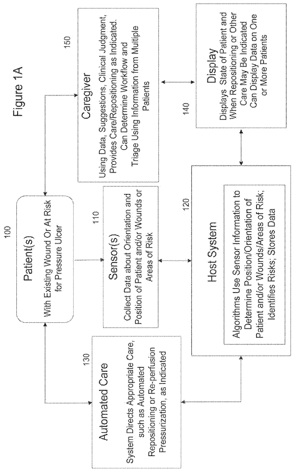
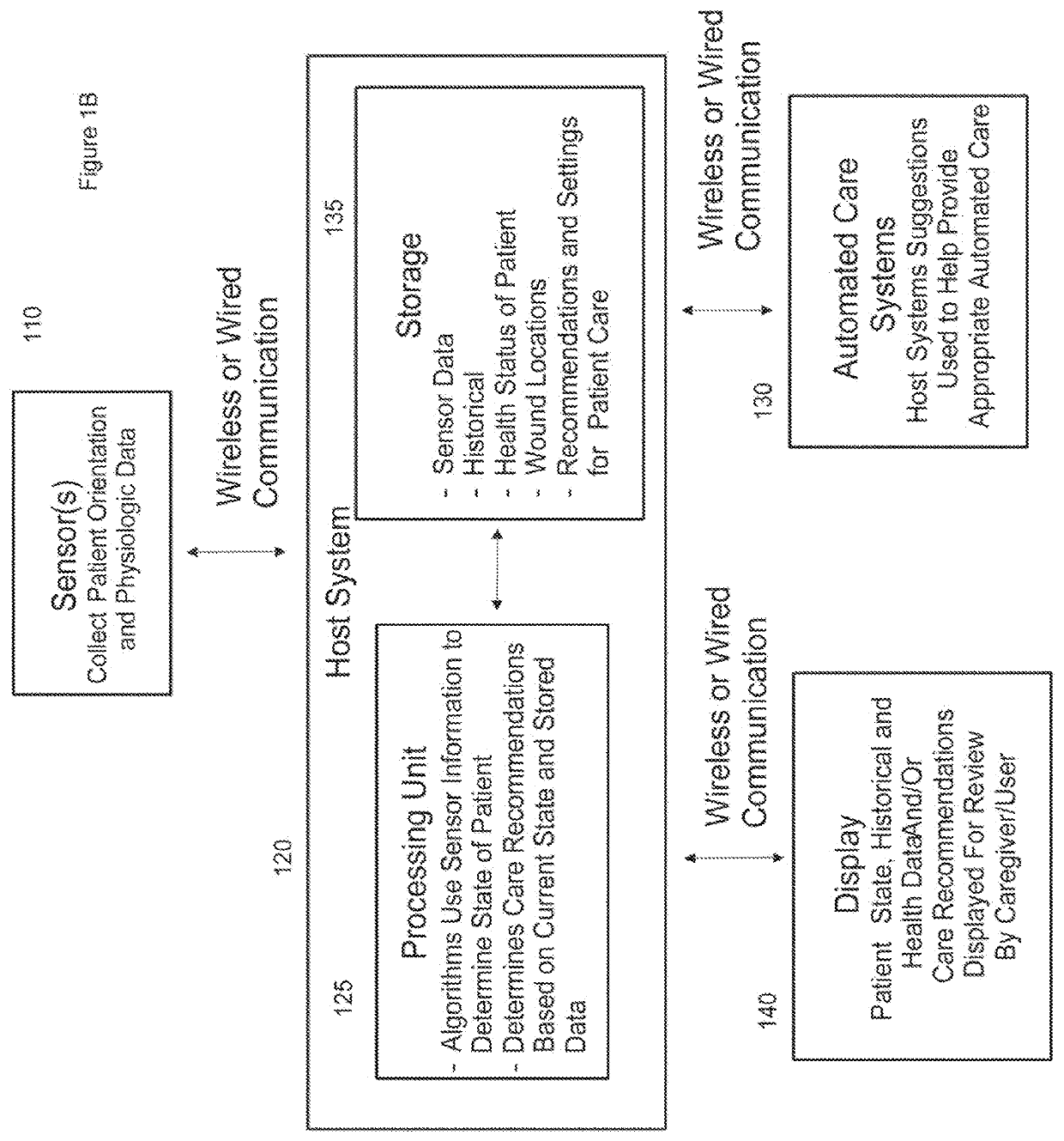
[0092]In an aspect of the present invention, an improved means for managing and coordinating patient turning protocols is provided. Referring first to FIGS. 1A-1B, an embodiment of a system in accordance with an aspect of the invention is illustrated in flow diagram form. A patient 100 requiring monitoring, and in at least some instances having an existing wound or being at risk for developing a pressure ulcer, is associated with one or more sensors 110. The sensors collect data about the orientation, position, and movement of the patient and / or wounds and / or areas of compromised tissue perfusion and / or areas of risk. The sensors communicate with a host system 120, typically a computer running at least one program for processing the incoming sensor information to determine the position or orientation or movements of a patient, wounds or areas of compromised tissue perfusion, or areas of risk on the patient. The program also uses historical and other data to analyze the sensor data a...


PUM


Abstract

A user-wearable sensor device may be configured to be directly or indirectly secured to a user or to an article worn by the user. The user-wearable sensor device may include at least one sensor configured to collect sensor data associated with an orientation of the user, a display unit including at least one LED or other visual indicator, a battery configured to provide power to at least the display unit, and a control system. The control system may be configured to determine the orientation of the user based on sensor data collected by the at least one sensor, maintain the display unit in a deactivated state in the absence of a defined activation input, detect a defined activation input, activate the deactivated display unit in response to detecting the defined activation input, and control the activated display unit based on the determined orientation of the user.

Description

RELATED APPLICATIONS[0001]This application is a continuation of U.S. patent application Ser. No. 15 / 601,593, filed May 22, 2017, which is a continuation-in-part of each of the following applications:[0002]U.S. patent application Ser. No. 15 / 189,086, filed Jun. 22, 2016;[0003]U.S. patent application Ser. No. 15 / 036,782, filed May 13, 2016, which is a U.S. national stage entry under 35 USC § 371 from international application PCT / US2014 / 66016 filed Nov. 17, 2014, which claims priority to the following U.S. Provisional Applications: (i) U.S. Ser. No. 62 / 047,642 filed Sep. 8, 2014 and (ii) U.S. Ser. No. 61 / 905,106 filed Nov. 15, 2013;[0004]U.S. patent application Ser. No. 15 / 028,018, filed Apr. 7, 2016, which is a U.S. national stage entry under 35 USC § 371 from international application PCT / US2014 / 59756 filed Oct. 8, 2014;[0005]U.S. patent application Ser. No. 14 / 543,887, filed Nov. 17, 2014, which claims priority to the following U.S. Provisional Applications: (i) U.S. Ser. No. 62 / 04...

Claims


Application Information

Patent Timeline
Patent Type & Authority Patents(United States)
IPC IPC(8): A61B5/11G16H50/20H04W4/80A61B5/00A61B5/0205A61G7/00A61G7/057G16H70/20H04W4/02G16H40/67G16H50/30G16H40/63A61B5/024A61B5/026A61B5/0531A61B5/08A61B5/113A61B5/145A61B5/1455A61B7/00
CPCA61B5/1115A61B5/002A61B5/0024A61B5/02055A61B5/1113A61B5/6801A61B5/6843A61B5/7275A61B5/7282A61B5/742A61G7/001A61G7/057G16H40/63G16H40/67G16H50/20G16H50/30G16H70/20H04W4/026H04W4/80A61B5/0075A61B5/024A61B5/0261A61B5/0531A61B5/0816A61B5/113A61B5/1116A61B5/1117A61B5/1118A61B5/14539A61B5/14551A61B5/447A61B5/4833A61B5/6892A61B5/7246A61B7/00A61B2560/0242A61B2562/029A61B2562/0214A61B2562/0219A61B2562/0223A61B2562/0247A61B2562/0261A61B2562/043A61G2203/42A61G2203/46H04W4/38
Inventor LARSON, BARRETTWECKWERTH, MARK
Owner LEAF HEALTHCARE
Learn More