Method for automatically restoring a calibrated state of a projection system

a projection system and automatic restoration technology, applied in the field of automatic restoration of the calibrated state of the projection system, can solve the problems of affecting the accuracy of the calibration state the inability of prior art solutions to allow a recalibration of the multiprojector system, and the complexity of setting up a large-area projection, etc., to achieve simple and error-free alignment

Active Publication Date: 2022-03-22
DOMEPROJECTION COM GMBH
View PDF10 Cites 0 Cited by
  • Summary
  • Abstract
  • Description
  • Claims
  • Application Information

AI Technical Summary

Benefits of technology

[0030]It is an object of the invention to provide a method for automatically restoring a calibrated state of a projection system, which enables simple and error-free alignment of a projection system in an originally calibrated error-free state of the projection system.

Problems solved by technology

Setting up a large-area projection, consisting of several partial projections or partial images, is complex.
However, a camera-based system requires demanding prerequisites to achieve high quality results.
This prior art solution disadvantageously does not allow a recalibration of the multiprojector system.
This prior art solution disadvantageously also does not permit recalibration of the multiprojector system.
Such large-area projections often do not have long-time stability.
However, this is time-consuming and requires expert knowledge.
The method described in the aforementioned publication is limited to piecewise smooth, vertically extruded projection surfaces.
The limitations listed below can limit the accuracy of a restoration and must be taken into account in a restoration.
If the large-area projection cannot be completely viewed by a camera in camera-based systems, the accuracy is a limited due to a view restriction.
The accuracy can be further limited by inaccuracies of the newly measured markers.
This limitation occurs, for example, in the event that the camera had to be arranged in such a way that it is placed outside the observer's field of vision.
For example, when only one camera is used and the camera image is fully utilized right into the corners of the camera image, the accuracy of the camera may be limited due to the lower quality of the camera optics in the peripheral areas of the lens.
A limitation of the accuracy may also be caused by a limited or inadequate resolution of the camera or the optics.
Inaccuracies in determining the position of the camera in the camera-based system, for example due to shifted reference marks such as laser markers, may also limit the accuracy.

Method used


Image

  • Method for automatically restoring a calibrated state of a projection system
  • Method for automatically restoring a calibrated state of a projection system
  • Method for automatically restoring a calibrated state of a projection system

Examples


Embodiment Construction

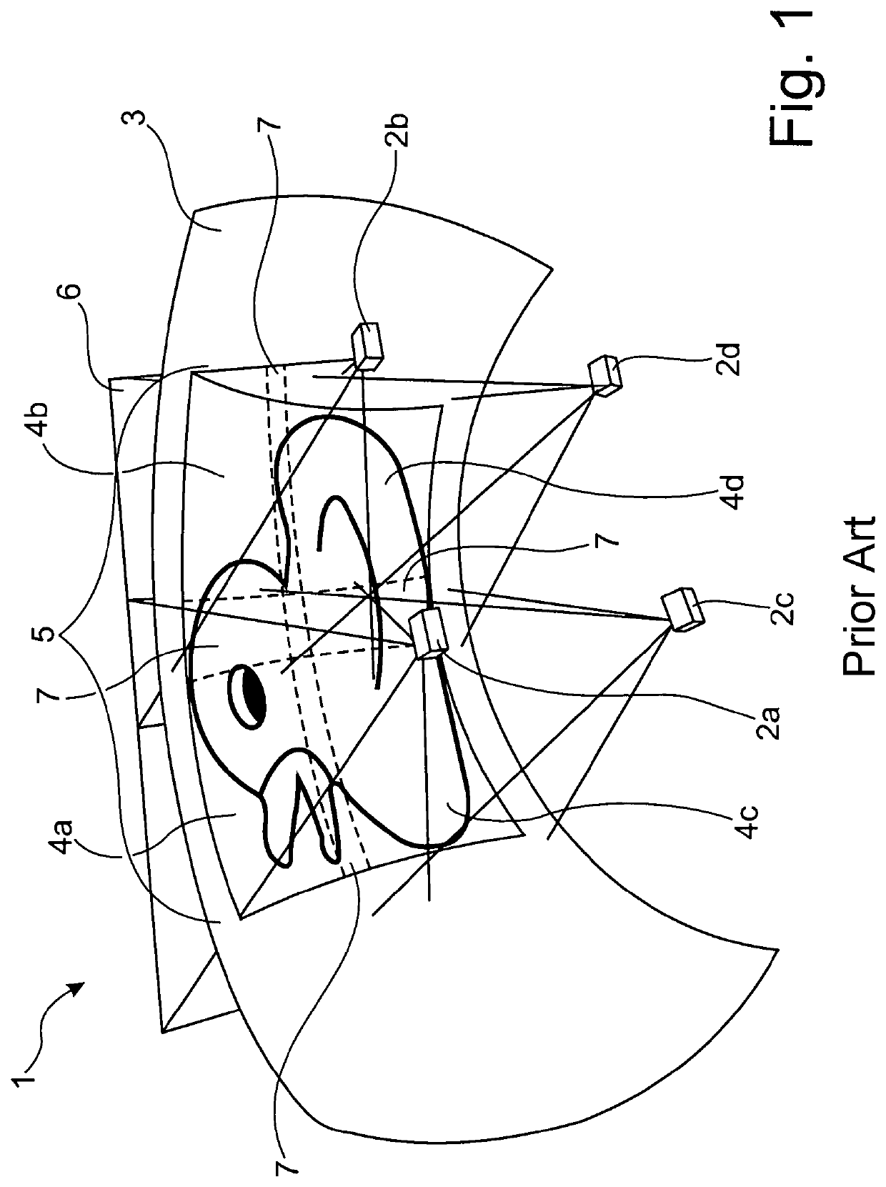
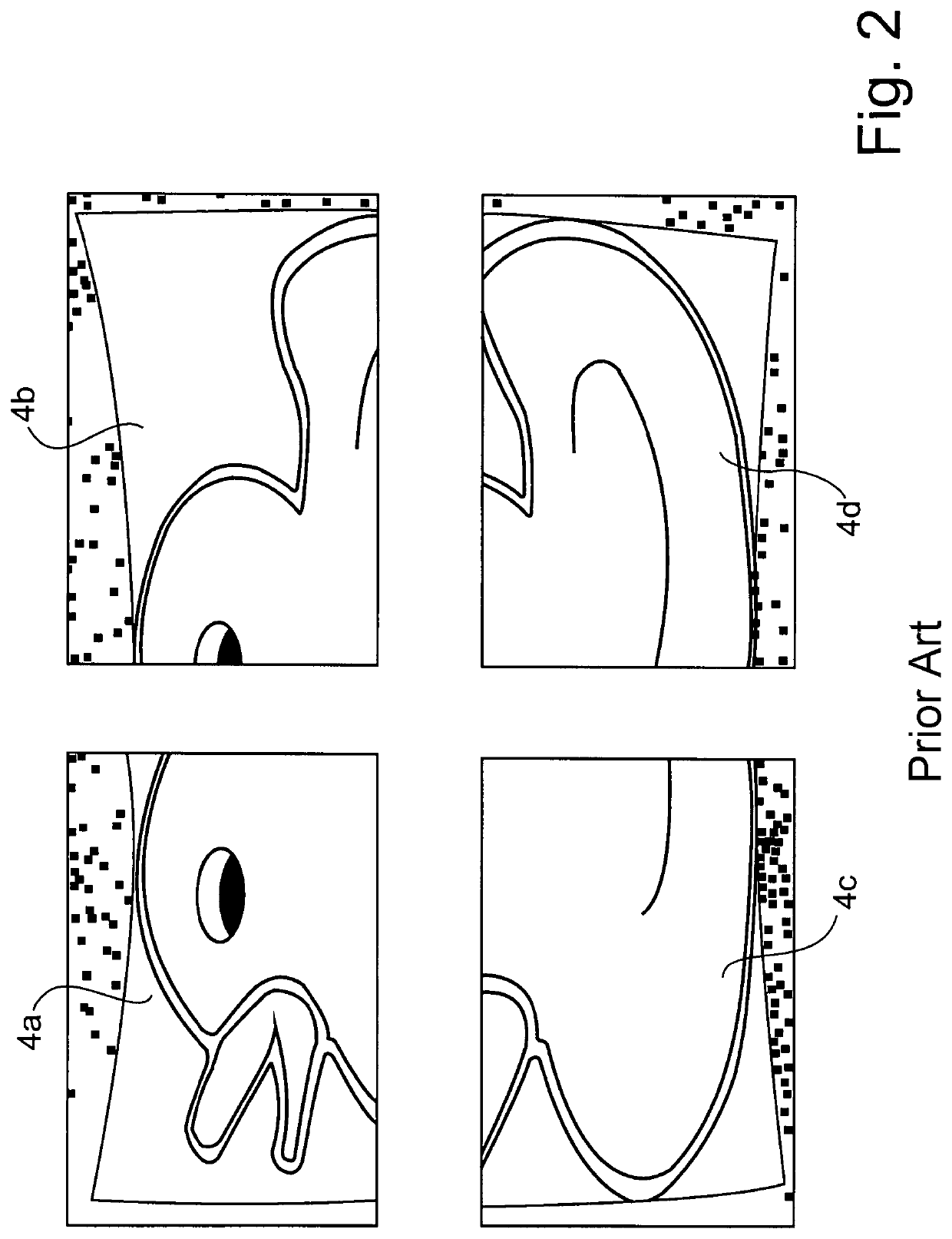
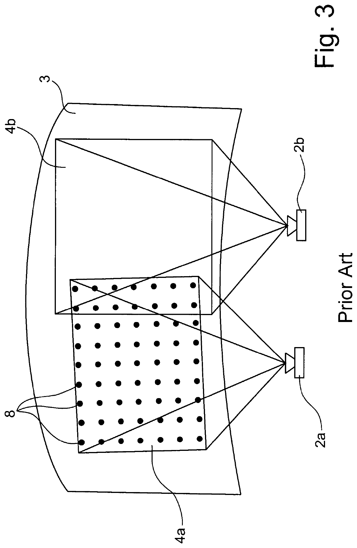
[0090]FIG. 1 shows a projection system 1 which has by way of example four projectors 2a, 2b, 2c, 2d. Each projector 2a, 2b, 2c, 2d generates a respective partial image 4a, 4b, 4c, 4d on the projection surface 3, which, when put together, result in a large-area projection 5. This large-area projection 5 is generated by creating between two adjacent partial images 4a, 4b, 4c, 4d a blend zone 7 in which image portions of the adjacent partial images 4a, 4b, 4c, 4d overlap. The image or video signals of the partial images 4a, 4b, 4c, 4d required for controlling the projectors 2a, 2b, 2c, 2d are generated in a suitable central signal generation unit, which is not described in detail here, since it has no effect on the embodiments of the present invention.

[0091]The required partial images 4a, 4b, 4c, 4d are originally generated in the signal generation unit in such a way that the large-area projection 5 projects with an error-free rendition only onto a flat projection surface 6, which is s...


PUM


Abstract

Method for automatically restoring a calibrated state of a projection system, allowing simple and error-free alignment of a projection system in an original error-free state of the system. A calibrated state of a projection system is automatically restored by calculating a position and orientation of at least one camera within the projection system, using fixed points, subsequently m times n markers (9′) are projected onto the projection area, using the markers by cameras to determine a reduced number, compared with the calibration, of second measurement points (QI′) that have one X, Y and Z coordinate each, the reduced number of second measurement points (QI′) is used to perform a calculation of the differences between the second measurement points (QI′) and the associated first measurement points (QI′), a displacement vector is formed, the association between the projector coordinates and 3D coordinates is adapted with the displacement vector.

Description

[0001]This is an application filed under 35 USC § 371 of PCT / DE2018 / 000327 filed on Nov. 10, 2018, claiming priority to DE 102017010683.5 filed on Nov. 17, 2017, each of which is herein incorporated by reference in its entirety.BACKGROUND OF THE INVENTION(1) Field of the Invention[0002]The invention relates to a method for the automatically restoring a calibrated state of a projection system, wherein when the projection system is calibrated, m times n markers are projected onto the projection surface, from which by using one or more cameras m times n first measuring points, each having an X, a Y and a Z coordinate located on the projection surface and thus on the surface of the 3D model, are determined, and wherein an association of projector coordinates with 3D coordinates (xpypi, XYZi) and a transformation of projector coordinates into mapping coordinates pKm and a transformation of mapping coordinates into projector coordinates mKp is provided.[0003]The present description relate...

Claims


Application Information

Patent Timeline
Patent Type & Authority Patents(United States)
IPC IPC(8): H04N9/31G03B21/14
CPCH04N9/3185G03B21/14H04N9/3147H04N9/3194
Inventor BEIER, DANIELGULAMHUSSENE, DANILOBODE, CHRISTOPHSTEINMANN, CHRISTIAN
Owner DOMEPROJECTION COM GMBH
Why Eureka
Try Eureka