Watercraft adjustable shaft spacing apparatus and related method of operation

Active Publication Date: 2022-03-29
PLATINUM MARINE INC
View PDF36 Cites 0 Cited by
  • Summary
  • Abstract
  • Description
  • Claims
  • Application Information

AI Technical Summary

Benefits of technology

This patent describes an outdrive system for watercraft that allows for adjustable vertical positioning of the propeller, which improves performance and efficiency. The system includes a standoff box and idler gears that transfer rotation from the input shaft to the transfer gear. The idler gears are engaged with the transfer gear and allow for constant rotation and force transfer as the drive unit moves between a raised and lowered mode. The standoff box and idler bracket can be easily adjusted to change the angle of the idler shaft relative to the drive unit, which allows for precise positioning of the propeller and minimizes energy loss. The outdrive system can be easily installed and assembled without disassembling or modifying the original drive system.

Problems solved by technology

For example, when an outdrive is tilted upward, the tilted angle of the propeller makes maneuvering the boat more difficult because the thrust is projected upward toward the water surface instead of being projected rearward, behind the boat.
Even with such tilt features an issue with conventional outdrives of inboard watercraft is that the vertical displacement of the propeller shaft and propeller is generally fixed and immovable relative to the bottom of the watercraft.
With this fixed relationship relative to the bottom of the watercraft, conventional outdrives fail to effectively provide vertical adjustment of the propeller shaft and propeller, and thus the thrust point.
While these standoff boxes are effective, they include special U-joint configurations, ball splines and / or split standoff boxes that can sometimes be complex to assemble and / or integrate with an existing OEM outdrive unit.

Method used


Image

  • Watercraft adjustable shaft spacing apparatus and related method of operation
  • Watercraft adjustable shaft spacing apparatus and related method of operation
  • Watercraft adjustable shaft spacing apparatus and related method of operation

Examples


Embodiment Construction

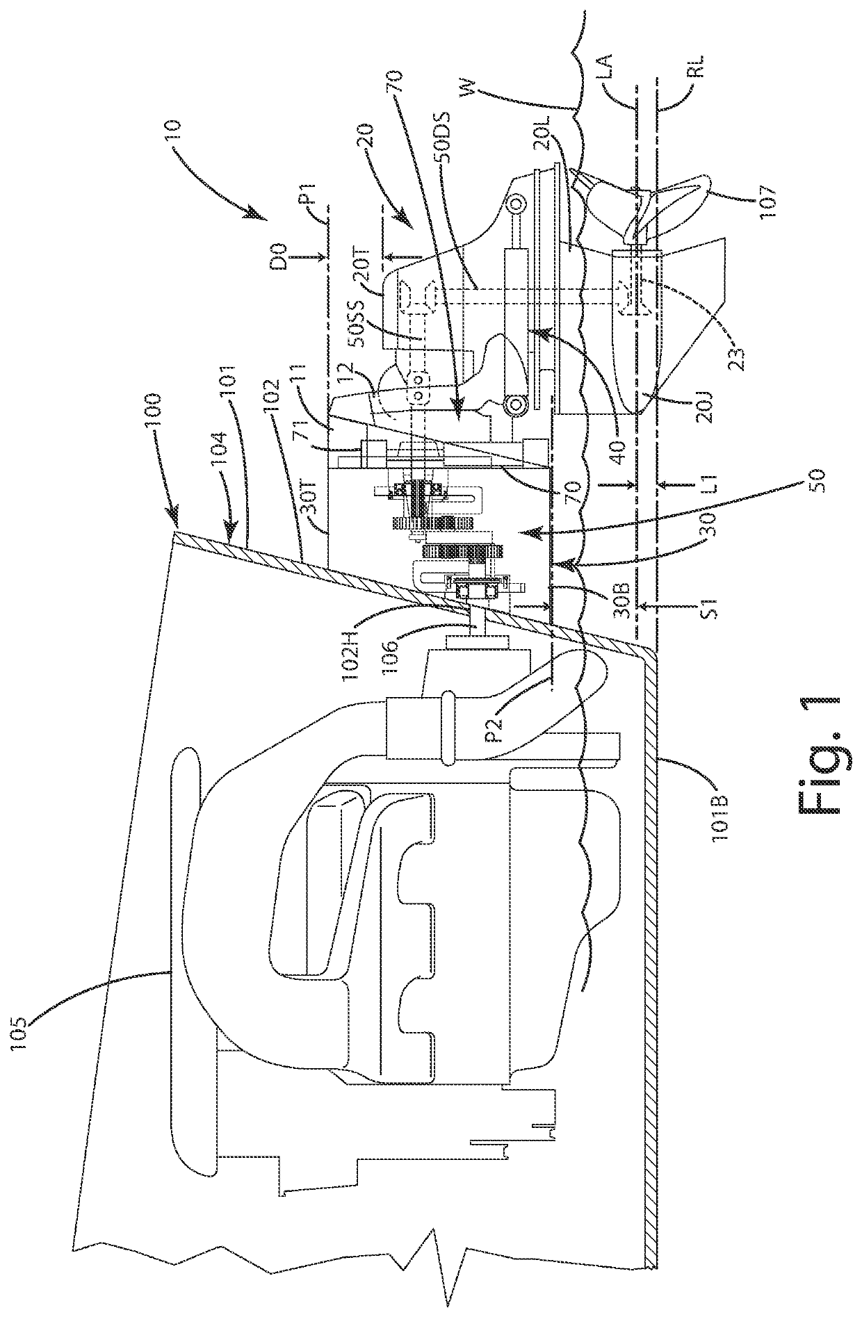
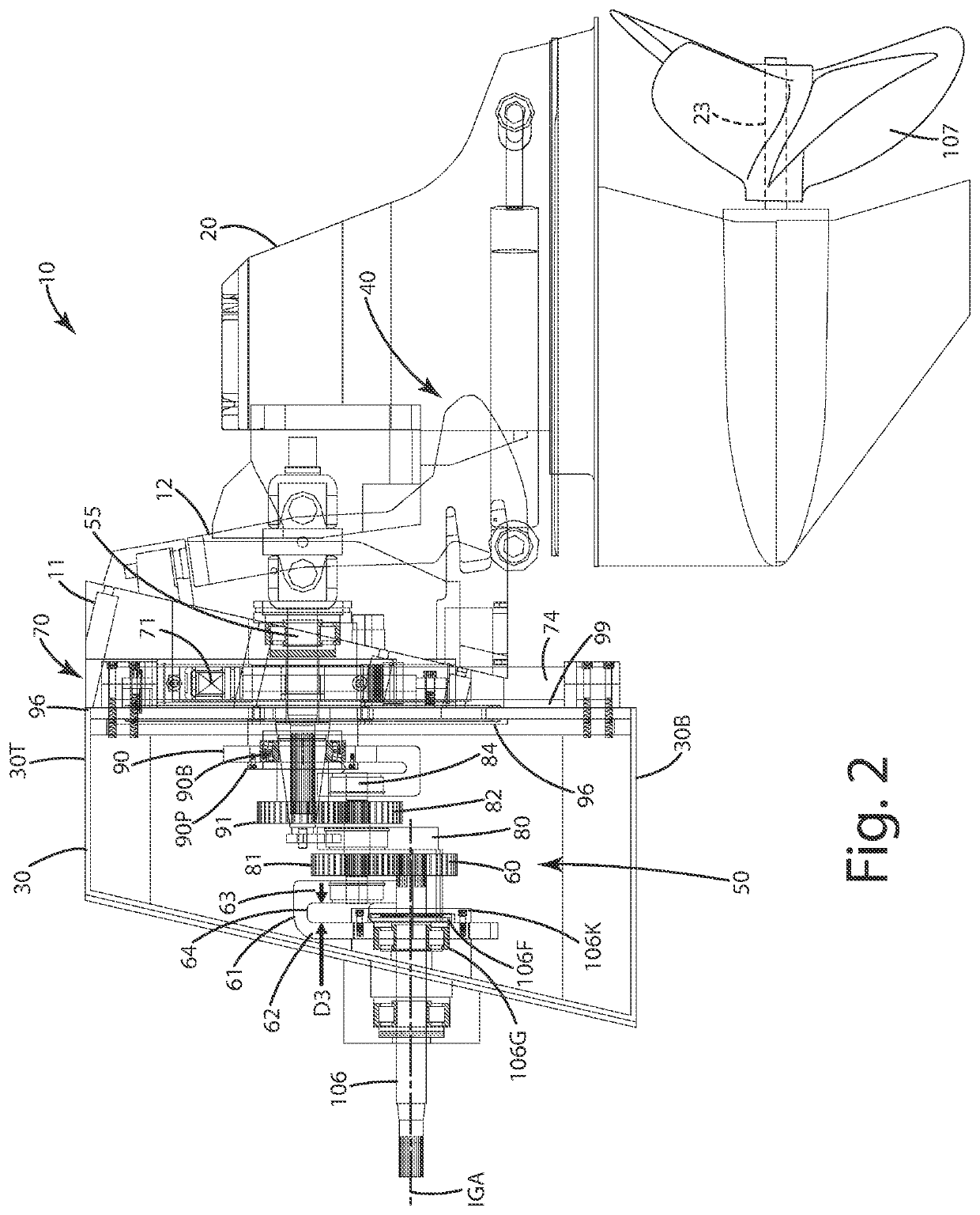
[0036]A current embodiment of the watercraft outdrive is illustrated in FIGS. 1-15, and generally designated 10. As illustrated in FIGS. 1-6, the outdrive 10 is joined with a watercraft 100. Although shown as a high performance boat, the watercraft 100 with which the outdrive 10 is used can be any type of marine vessel, for example, a recreational boat, a racing boat, a pontoon boat, a fishing vessel, a tanker or other type of commercial vessel, a submarine, a personal watercraft, an amphibious vehicle, an underwater exploration vehicle, or any other type of vessel that is propelled through or on water via a propeller.

[0037]The watercraft 100 includes a hull 101 having a stern 104 at which a transom 102 is located. The hull 101 also includes a bottom 101B. This bottom can coincide with or include a lowermost portion of the hull. The watercraft can include a reference line RL that extends rearward from the hull 101, and in particular, that extends from the lowermost portion of the tr...


PUM


Abstract

An outdrive for a marine vessel, such as a watercraft having an inboard engine, includes a standoff box configured to continuously provide power to the drive unit as the drive unit vertically moves from a raised mode to a lowered mode, thereby lowering a thrust point produced by a propeller, all while the watercraft is moving through water and while the propeller is producing thrust. The standoff box can include one or more idler gears that move via a system of brackets relative to an input gear and a transfer gear to maintain rotational engagement between the input gear and the transfer gear, which is joined with the drive unit to rotate the propeller. A related method also is provided.

Description

BACKGROUND OF THE INVENTION[0001]The present invention relates to watercraft, and more particularly to a watercraft outdrive that can move a propeller and its shaft relative to a watercraft bottom while the watercraft is under power.[0002]There is a variety of watercraft used in different activities. Some watercraft is used for commercial purposes, while others are used for recreation and / or competition. Many watercraft or boats are constructed to include an inboard motor. In such a construction, the engine of the boat is located inside the hull of the boat, while an outdrive projects rearward from the stern of the boat. The outdrive typically includes a transmission that transfers rotational forces from the engine to a propeller shaft and an associated propeller. Upon rotation, the propeller produces thrust to propel the boat through water.[0003]Conventional outdrives of inboard watercraft typically are constructed so that the outdrive can tilt about a pivot point tilt the propelle...

Claims


Application Information

Patent Timeline
IPC IPC(8): B63H23/06B63H5/125
CPCB63H23/06B63H5/1252
Inventor WOODY, CLARK M.
Owner PLATINUM MARINE INC
Why Eureka
Try Eureka