Supercharge Your Innovation With Domain-Expert AI Agents!

Watertight LED arrangement

a led arrangement and watertight technology, applied in the field of light-emitting solutions, can solve the problems of affecting the appearance of the external appearance, requiring end caps, and unable to produce several thousand meters economically in one piece, and achieve the effect of improving the light quality of led arrangements

Active Publication Date: 2022-03-29
SCHLUTER SYST LP
View PDF16 Cites 0 Cited by
  • Summary
  • Abstract
  • Description
  • Claims
  • Application Information

AI Technical Summary

Benefits of technology

The present invention is an LED arrangement and a method for manufacturing it that seeks to improve the light quality and eliminate certain disadvantages. The LED arrangement includes a sheath that bears directly against the LED board and has a cavity between the LEDs and the light emission wall. The LED board is angled to prevent liquid material from filling the cavity during manufacture. The sheath has protrusions that facilitate easy insertion into a U-shaped cross-section profile. The sheath is manufactured in two steps to create the cavity between the LED board and the upper sheath region. Different materials can be selected for the sheath regions. These technical improvements improve the uniformity of the emitted light, achieve a constant color temperature, and prevent liquid material from shifting the color location.

Problems solved by technology

One disadvantage, however, is that only several thousand meters can be produced economically in one piece.
Another disadvantage is the obligatory use of end caps.
On the one hand, these have to be connected to the sheath in a watertight manner, which is always a challenge.
In addition, end caps, even if made of a translucent material, change the light color in the region of the end cap, which interferes with the external appearance.
A further disadvantage is that the cable must always be provided in the area of an end cap.
A cable protruding at another position to the underside of the LED arrangement could only be produced with a very high additional effort.
One disadvantage, however, is that the manufacturing method is not yet sufficiently mature and / or controllable to be able to produce a light emission wall with a consistently high surface quality at low costs.
In contrast, LED boards embedded directly in the material of the sheath cause a shift of the color location depending on the layer thickness of the material above the LEDs, which is not desirable.
If, for example, the color shade of the coloring is chosen according to the color shade of the tiles surrounding the LED arrangement in the installed state, a very inconspicuous appearance of the LED arrangement is achieved when the LEDs are switched off.

Method used


Image

  • Watertight LED arrangement
  • Watertight LED arrangement
  • Watertight LED arrangement

Examples


Embodiment Construction

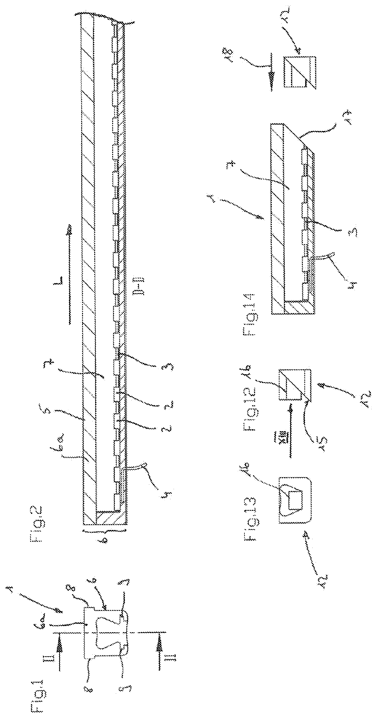
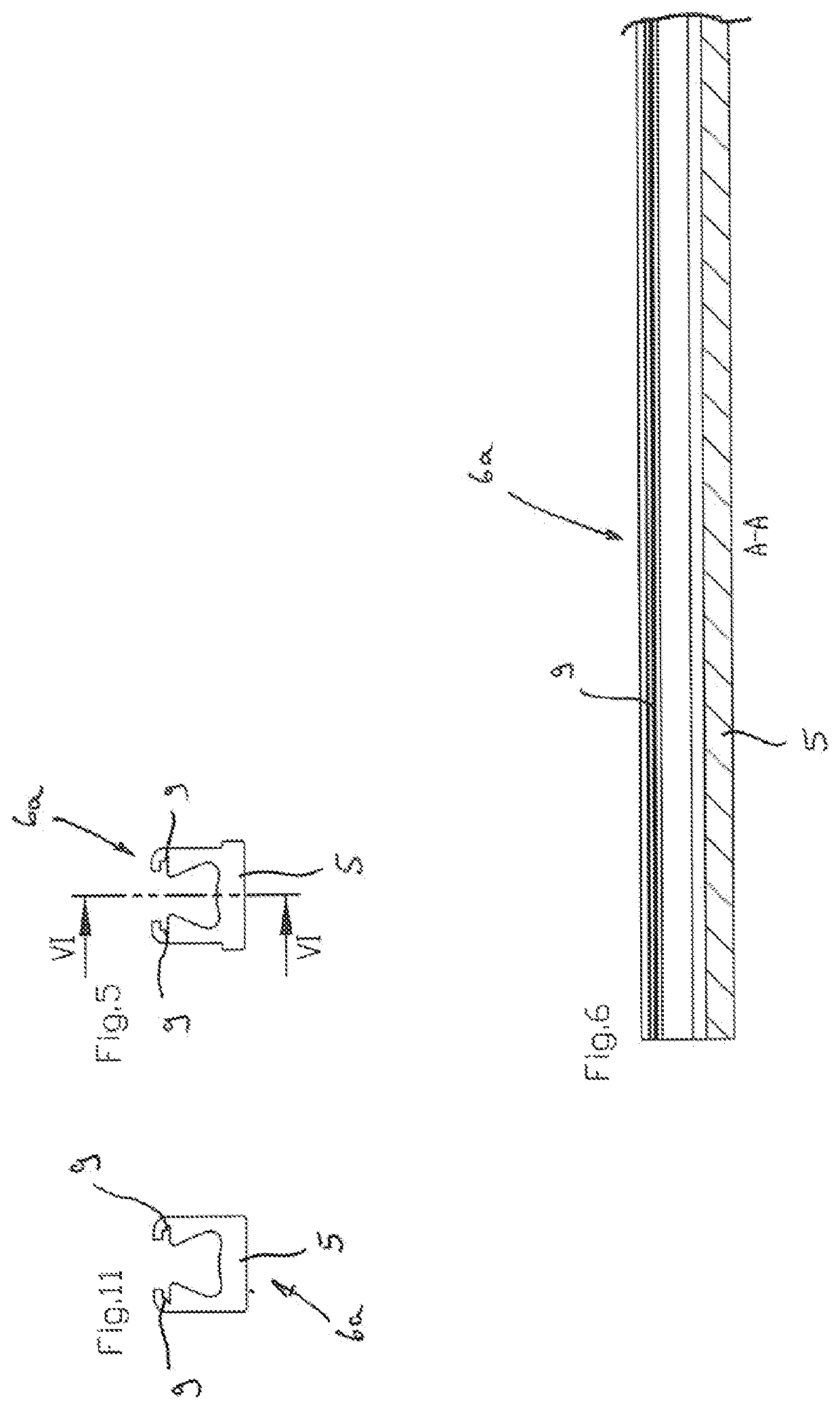
[0055]Reference will now be made to the exemplary embodiments illustrated in the drawings, and specific language will be used herein to describe the same. It will nevertheless be understood that no limitation of the scope of the technology is thereby intended. Alterations and further modifications of the inventive features illustrated herein, and additional applications of the principles of the technology as illustrated herein, which would occur to one skilled in the relevant art and having possession of this disclosure, are to be considered within the scope of the technology.

Definitions

[0056]As used herein, the singular forms “a” and “the” can include plural referents unless the context clearly dictates otherwise. Thus, for example, reference to “an LED” can include one or more of such items, if the context so dictates.

[0057]As used herein, the term “substantially” refers to the complete or nearly complete extent or degree of an action, characteristic, property, state, structure, i...


PUM

PropertyMeasurementUnit
lengthaaaaaaaaaa
lengthaaaaaaaaaa
distanceaaaaaaaaaa

Abstract

A watertight LED arrangement (1) is provided that extends in a longitudinal direction (L). A strip-shaped LED board (3) is provided with a multiplicity of LEDs (2) on its upper side and at least one cable (4) is electrically connected to the LED board (3). A one-piece, elastically formed watertight sheath (6) surrounds the LED board (3) and defines a light emission wall (5) at least on its upper side opposite the LEDs (2), the sheath (6) receiving the LED board (3) in a form-fitting manner. A cavity (7) extends in the longitudinal direction (L) between the upper side of the LED board (3) and the light emission wall (5). At least a portion of a sealing element (10a) extends from the LED board (3) toward the light emission wall (5) and defines an edge of the cavity (7).

Description

PRIORITY CLAIM[0001]This is a continuation-in-part of U.S. patent application Ser. No. 16 / 514,737, filed Jul. 17, 2019, which claims priority of and to German Patent Application Serial No. 10 2018 117 343.1, filed Jul. 18, 2018, each of which is hereby incorporated herein by reference in its entirety.BACKGROUND OF THE TECHNOLOGYField of the Technology[0002]The present technology relates generally to lighting solutions for use in wet environments.Related Art[0003]The present invention relates to a watertight LED arrangement extending in a longitudinal direction, having a strip-shaped LED board provided with a multiplicity of LEDs on its upper side, at least one cable electrically connected to the LED board and a one-piece, elastically formed watertight sheath which surrounds the LED board and defines a light emission wall at least on its upper side opposite the LEDs, the sheath receiving the LED board in a form-fitting manner.[0004]Such LED arrangements are known in the prior art in ...

Claims


Application Information

Patent Timeline
Patent Type & Authority Patents(United States)
IPC IPC(8): F21V31/00F21K9/90F21V23/00F21S4/28F21Y115/10
CPCF21V31/005F21K9/90F21S4/28F21V23/001F21V23/005F21Y2115/10F21V3/062F21V15/01F21V27/02F21Y2103/10
Inventor SCHLUTER, WERNER
Owner SCHLUTER SYST LP
Features
  • R&D
  • Intellectual Property
  • Life Sciences
  • Materials
  • Tech Scout
  • Unparalleled Data Quality
  • Higher Quality Content
  • 60% Fewer Hallucinations
Learn More