Wireless power transmission method and device therefor
a power transmission and wireless technology, applied in wireless communication, transmission path sub-channel allocation, transportation and packaging, etc., can solve the problems of not being able to adjust a guaranteed power level initiatively directly, power transmitters may not detect foreign objects in charge regions or magnetic field regions,
Active Publication Date: 2022-03-29
LG ELECTRONICS INC
View PDF25 Cites 5 Cited by
- Summary
- Abstract
- Description
- Claims
- Application Information
AI Technical Summary
Benefits of technology
This patent describes a power transmitter that can adjust its power level based on the surrounding environment, allowing for a dynamic and appropriate adjustment. The power transmitter can also transmit full packets without colliding with a pre-defined Qi communication protocol in the WPC standard or with packets transmitted by a power receiver.
Problems solved by technology
Since a sender or a master that initiates / leads communication in a communication protocol between a power transmitter and a power receiver defined in a current WPC standard is the power receiver, the power transmitter may transmit only a response to a request of the power receiver, and as a result, the power transmitter may not detect foreign objects in a charge region (or a magnetic field region) or may not adjust a guaranteed power level initiatively directly at a desired timing even though a charging environment is changed.
Method used
View moreImage
Smart ImageViewing Examples
Examples
Embodiment Construction
[0233]Various embodiments are described in a best mode for carrying out the present invention.
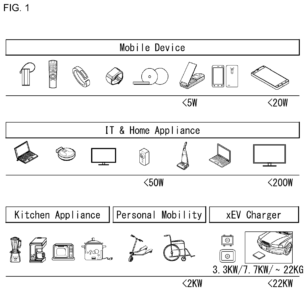
[0234]The present invention may be applied to various wireless charging technologies.
Login to View More PUM
 Abstract
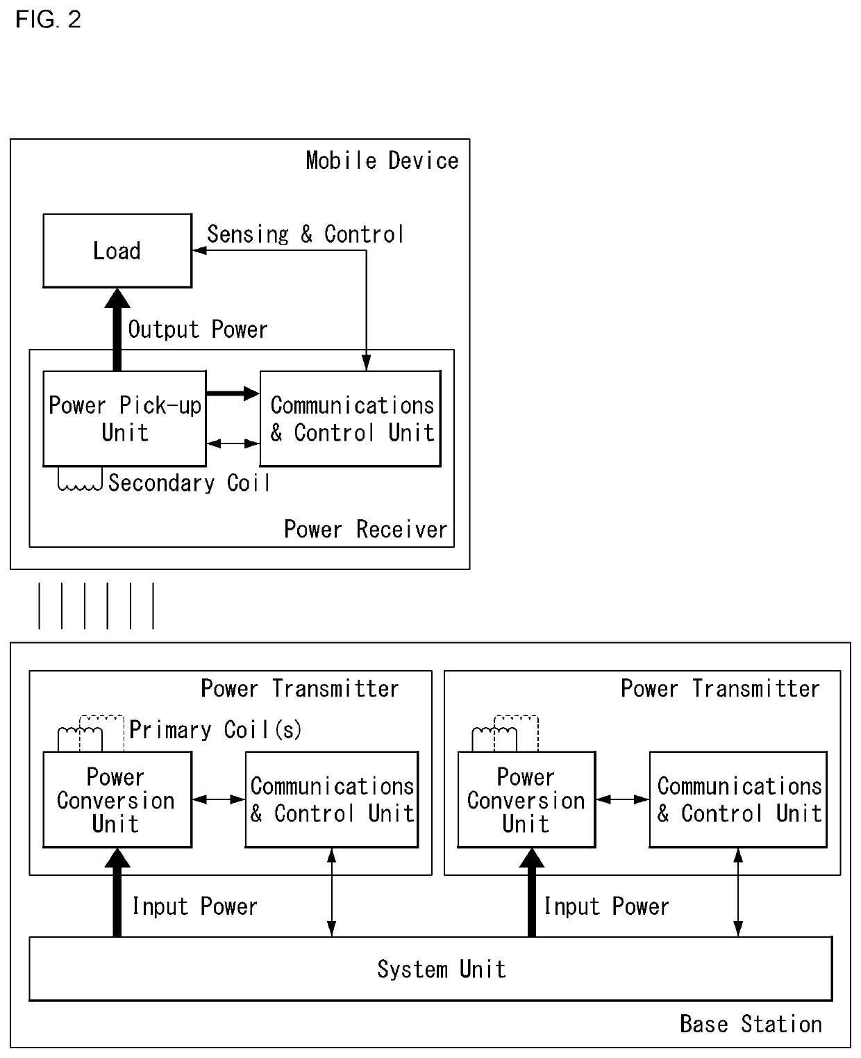
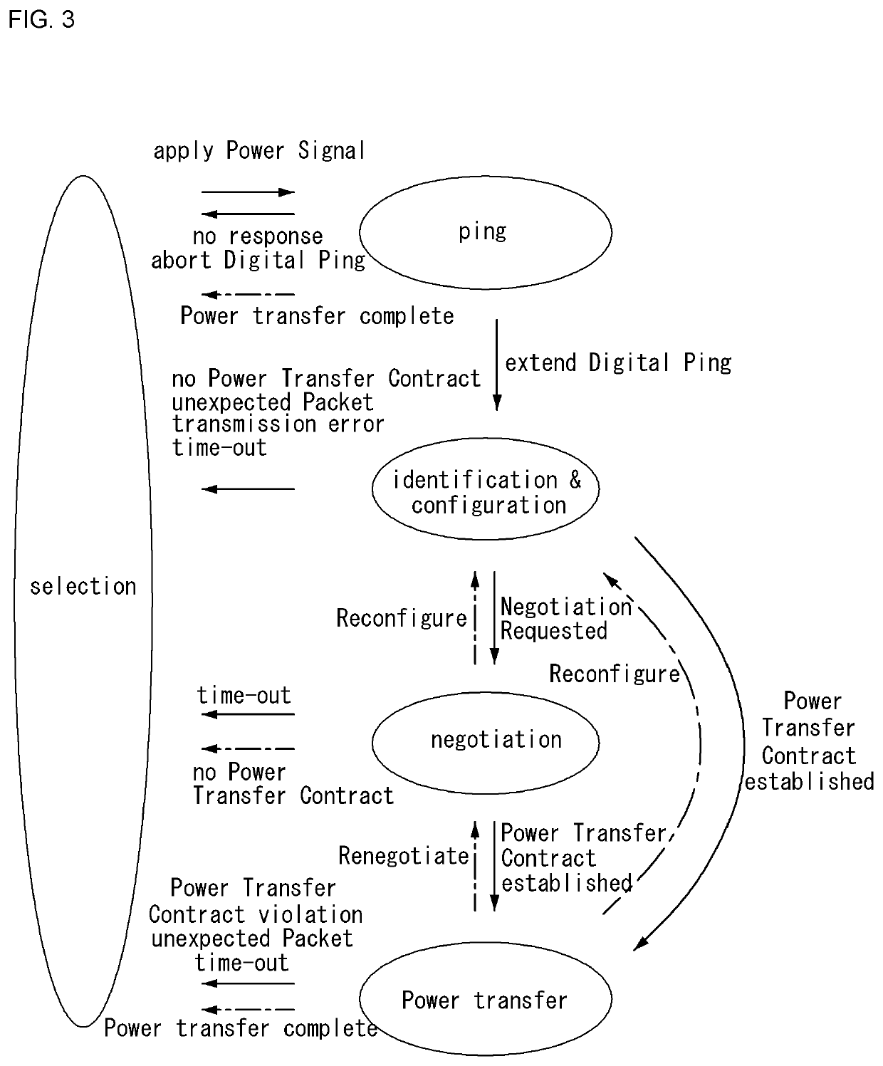
A wireless power transmission method executed by a power transmitter comprising multi-coils, according to one embodiment of the present invention, comprises the steps of: detecting a second power receiver while transmitting power to a first power receiver; determining at least one primary coil adequate for power transmission; by using the determined at least one primary coil, determining whether the second power receiver supports a shared mode protocol; and if the second power receiver supports the shared mode protocol, transmitting power to the first and second power receivers according to the shared mode protocol, wherein the shared mode protocol may be a protocol for simultaneously managing information exchanges between the power transmitter and multiple power receivers.
Description
CROSS-REFERENCE TO RELATED APPLICATIONS[0001]This application is a continuation of U.S. application Ser. No. 16 / 308,325, filed on Dec. 7, 2018, which is a National Stage Application under 35 U.S.C. § 371 of International Application No. PCT / KR2017 / 005941, filed on Jun. 8, 2017, which claims the benefit of U.S. Provisional Application No. 62 / 471,896, filed on Mar. 15, 2017, U.S. Provisional Application No. 62 / 425,042, filed on Nov. 21, 2016, U.S. Provisional Application No. 62 / 413,947, filed on Oct. 27, 2016, and U.S. Provisional Application No. 62 / 347,575, filed on Jun. 8, 2016. The disclosures of the prior applications are incorporated by reference in their entirety.[0002]The present invention relates to a wireless power transmission method and a device therefor.BACKGROUND ART[0003]A contactless wireless charging method is an energy transfer method for electromagnetically transferring energy without using a wire in a method for sending energy through an existing wire so that the en...
Claims
Login to View More Application Information
Patent Timeline
 Patent Type & Authority Patents(United States)
IPC IPC(8): H02J50/80H02J50/10H02J50/60H02J7/02H04L5/00H04B5/00
CPCH02J50/80H02J7/02H02J7/025H02J50/10H02J50/60H04L5/0055H04B5/0037H02J7/00034H02J7/00045H04L63/0823H04W12/069H04B5/24H04B5/79
Inventor PARK, YONGCHEOL
Owner LG ELECTRONICS INC
Features
- R&D
- Intellectual Property
- Life Sciences
- Materials
- Tech Scout
- Unparalleled Data Quality
- Higher Quality Content
- 60% Fewer Hallucinations
Learn More Browse by: Latest US Patents, China's latest patents, Technical Efficacy Thesaurus, Application Domain, Technology Topic, Popular Technical Reports.
© 2025 PatSnap. All rights reserved.Legal|Privacy policy|Modern Slavery Act Transparency Statement|Sitemap|About US| Contact US: help@patsnap.com


