Spindle gearbox and drive unit of an electric seat drive

a technology of electric seat drive and drive unit, which is applied in the direction of gearing details, movable seats, gearing, etc., can solve the problems of large restrictions on the use of identical parts in different applications by way of mounting concept, and the inability to use the drive for both a left-hand and a right-hand, so as to reduce the requirement for additional components

Active Publication Date: 2020-10-06
ROBERT BOSCH GMBH
View PDF19 Cites 3 Cited by
  • Summary
  • Abstract
  • Description
  • Claims
  • Application Information

AI Technical Summary

Benefits of technology

[0004]The spindle mechanism according to the invention of an electric seat drive makes a reduction of the multiplicity of parts possible, as a result of which, in particular, a cost reduction is achieved. In particular, a mechanism housing of the spindle mechanism permits both a left-hand embodiment and a right-hand embodiment of the spindle mechanism. The spindle mechanism can therefore be used in a modular manner. Moreover, a crash strength can be set in a modular manner, by it being possible for individual components to be manufactured from materials with a different strength. The spindle mechanism according to the invention of an electric seat drive comprises a mechanism housing, a threaded spindle, and a first cover and a second cover. The mechanism housing is configured for mounting a worm gear and a worm, and can be in one piece or in multiple pieces. It is provided here that the worm meshes in the worm gear. The threaded spindle is connected to the worm gear. In this way, a transmission of force and / or a transmission of torque between the worm gear and a threaded spindle are / is made possible. The first cover and the second cover are fastened to the mechanism housing parallel to one another. In particular, the first cover and the second cover extend parallel to the worm gear. It is provided here that the threaded spindle is guided through the first cover. It is preferred, in particular, that the first cover and the second cover cover the worm gear. It is provided, moreover, that the first cover is fastened to the mechanism housing independently of the second cover. The second cover has, in particular, a variable connection geometry, via which the spindle mechanism can be fastened to a component of a vehicle or of a seat. Since the second cover is a separate component, said connection geometry can be of different configuration for different applications. The first cover has, in particular, a seal element, by way of which the first cover can be sealed with respect to the threaded spindle which is guided through the first cover. As a result of the fastening of the first cover independently of the second cover, the spindle mechanism is of modular construction, since the first cover can be replaced, in particular, independently of the second cover. In this way, the first cover and / or the second cover can be individually adapted to existing boundary conditions, in particular with regard to operating forces and / or crash forces which are to be absorbed.
[0005]The mechanism housing is preferably of symmetrical configuration with respect to a plane perpendicularly with respect to the threaded spindle. The plane of symmetry lies, in particular, centrally in the mechanism housing between the first cover and the second cover. It is made possible in this way that both the first cover and the second cover can be attached on all sides of the mechanism housing, as a result of which the threaded spindle can be mounted on all sides of the mechanism housing. In this way, in particular, mounting in the left-hand and right-hand embodiments in the case of the use of the same spindle mechanism is made possible.

Problems solved by technology

For instance, it is firstly not possible to use the drive for both a left-hand and a right-hand embodiment.
Moreover, the modularity and therefore the use of identical parts in different applications by way of a mounting concept as in the prior art are greatly restricted.

Method used


Image

  • Spindle gearbox and drive unit of an electric seat drive

Examples


Embodiment Construction

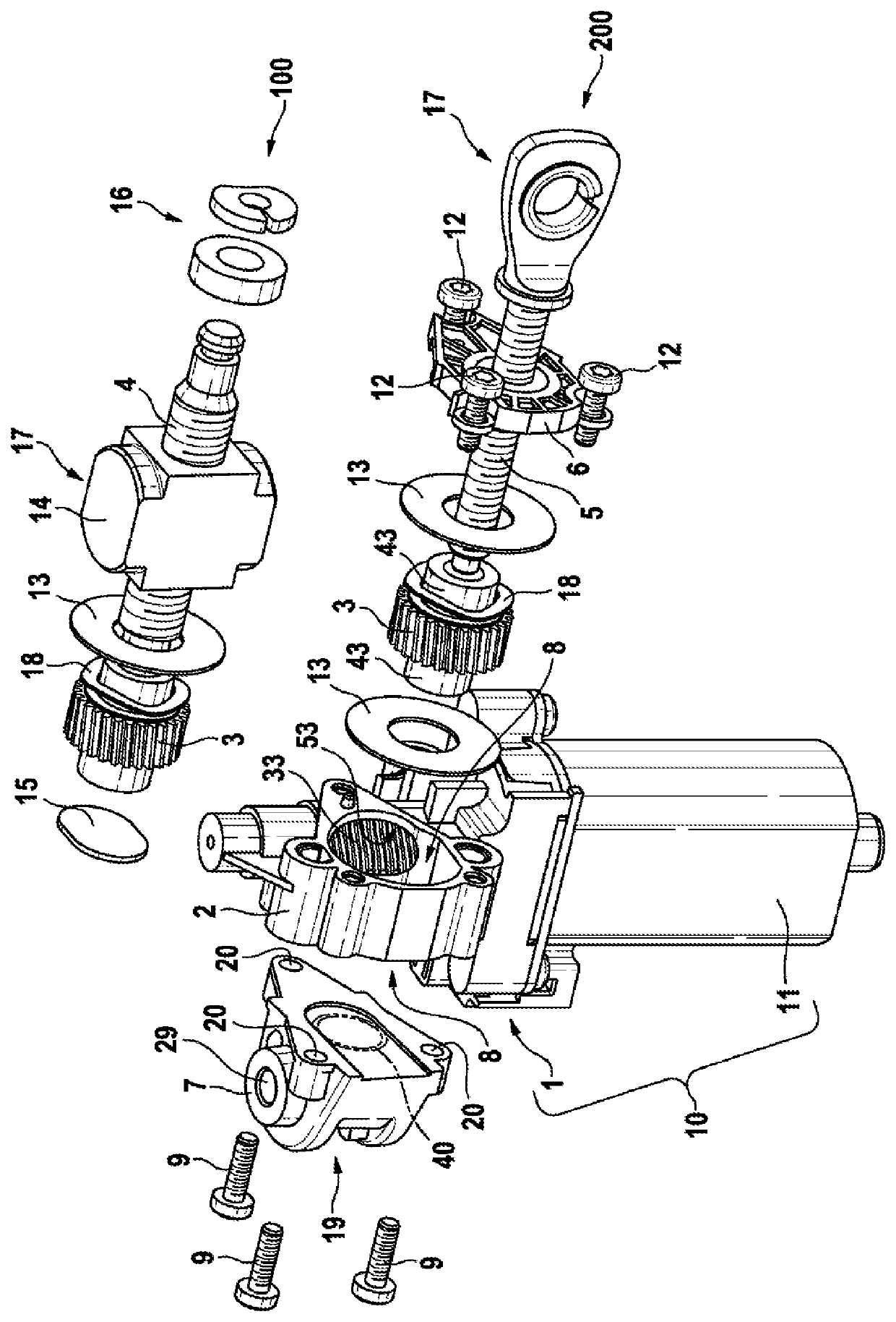
[0021]FIG. 1 shows a drive unit 10 in accordance with one embodiment of the invention. The drive unit 10 comprises a spindle mechanism 1 and a drive motor 11. It is provided here that a seat adjustment of a seat of a motor vehicle is made possible by way of the drive unit.

[0022]In order to adjust the seat, the spindle mechanism 1 has a mechanism housing 2, in which both a worm gear 3 and a worm 33 can be mounted. The worm 33 can be driven by the drive motor 11 and is arranged, in particular, on the armature shaft of the latter. The worm 33 engages through a lateral opening 53 in the mechanism housing 2 and meshes with the worm gear 3, with the result that a rotation can be transmitted to the worm gear 3. In turn, a threaded spindle 4, 5 can be driven by the worm gear 3, via which threaded spindle 4, 5 the seat can be moved.

[0023]The mechanism housing 2 has a drive opening (not visible), through which a connection between the drive motor 11 and the worm is made possible. The drive op...


PUM


Abstract

The invention relates to a spindle gearbox (1) of an electric seat drive, comprising a gearbox housing (2) for mounting a worm gear (3) and a worm, the worm meshing with the worm gear (3), a threaded spindle (4, 5) connected to the worm gear (3), a first lid (6), and a second lid (7), wherein the first lid (6) and the second lid (7) are fastened parallel to one another on the gearbox housing (2). The threaded spindle (4, 5) is guided through the first lid (6), and the first lid (6) is fastened on the gearbox housing (2) independently of the second lid (7).

Description

BACKGROUND OF THE INVENTION[0001]The present invention relates to a spindle mechanism for an electric seat drive. Moreover, the invention relates to a drive unit for an electric seat drive. In particular, the electric seat drive can be used in a vehicle.[0002]The prior art has disclosed spindle motors, via which a seat can be adjusted electrically. If a seat of this type is used in a vehicle, the spindle motor has to be capable of absorbing both operating forces and crash forces via a mechanism housing. Here, the mechanism housing has a customer interface, via which the mechanism housing can be fastened to further components of the vehicle or of the seat. A mounting direction, in which the spindle is inserted into the mechanism housing, is usually oriented perpendicularly with respect to the spindle axis.[0003]A design as shown in the prior art has some disadvantages, however. For instance, it is firstly not possible to use the drive for both a left-hand and a right-hand embodiment....

Claims


Application Information

Patent Timeline
Patent Type & Authority Patents(United States)
IPC IPC(8): F16H25/24B60N2/02B60N2/90F16H25/20F16H57/039F16H57/02
CPCF16H57/039F16H25/20B60N2/0232B60N2/929F16H2057/02082F16H2025/2084B60N2002/0236B60N2002/024F16H2025/2031F16H2025/209B60N2/02253B60N2/02258B60N2/02246
Inventor ANGERER, CHRISTOF
Owner ROBERT BOSCH GMBH
Why Eureka
Try Eureka