Welding current source for a welding apparatus

a current source and welding technology, applied in welding apparatuses, welding electric supplies, manufacturing tools, etc., can solve problems such as damage to the apparatus, and achieve the effect of low current strength and high current strength

Inactive Publication Date: 2008-02-14
LORCH SCHWEISSTECHNIK GMBH
View PDF14 Cites 0 Cited by
  • Summary
  • Abstract
  • Description
  • Claims
  • Application Information

AI Technical Summary

Benefits of technology

[0010] In a further advantageous embodiment of the solution according to the invention, the second switchover mechanism comprises switchover elements for several load circuits, with which the load circuits can be connected either in parallel or in series. Variation of the current strength and hence adaptation to the respective, country-specific power input voltage are thereby rendered possible without any difficulty, so that, for example, in the case of an electric power network with high voltage and low current strength, conversion to a current with low voltage and hence high current strength is possible, as is required for welding. Thus, in accordance with Kirchhoff's Current Law, in the case of a parallel connection the sum of the partial currents is equal to the total current, and the voltage is of identical size in all load circuits, whereas in the case of a series connection, in accordance with Kirchhoff's Voltage Law, the sum of the partial voltages is equal to the total voltage, and the current strength is of identical size at all points of the series connection. Both the voltage and the current strength can therefore be adapted in a simple way to the respective, country-specific requirements.

Problems solved by technology

Both modes of execution do, however, require a separate replugging or switching-over or reconnecting of the control / load circuits, which involves considerable operating expenditure and, in addition, can easily result in damage to the apparatus if the switching-over or manual replugging is carried out in a faulty manner.

Method used


Image

  • Welding current source for a welding apparatus
  • Welding current source for a welding apparatus
  • Welding current source for a welding apparatus

Examples


Embodiment Construction

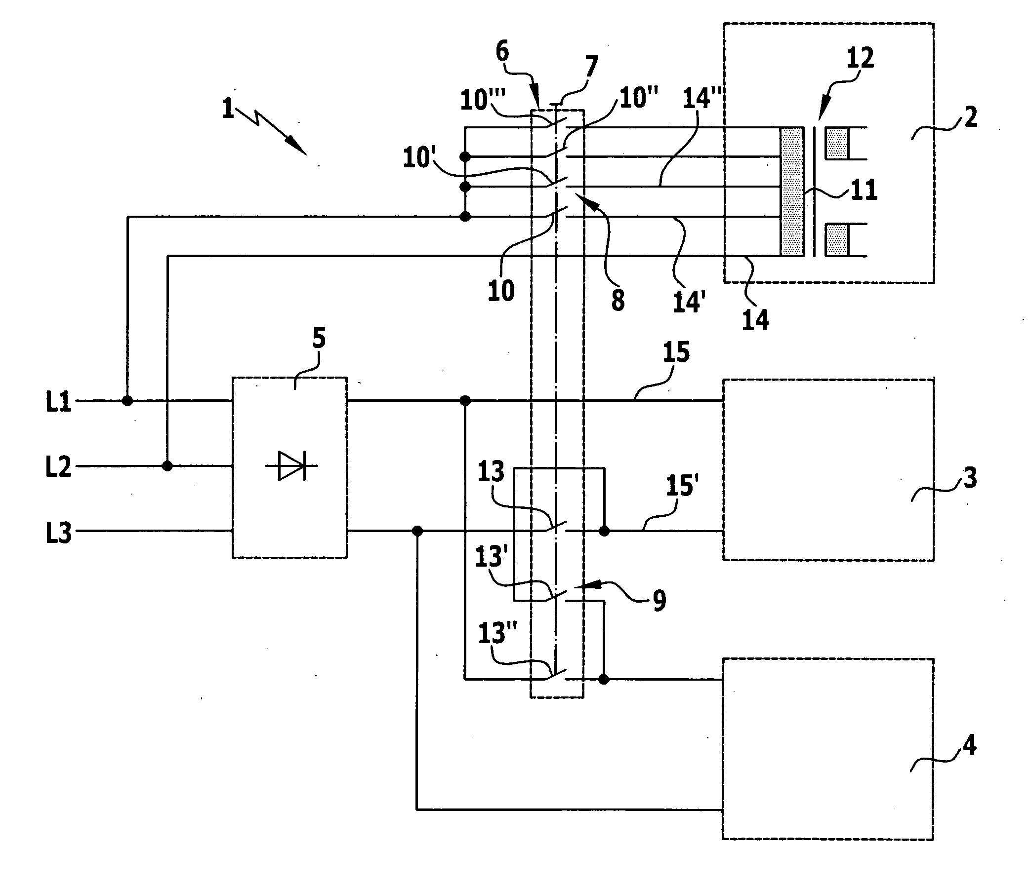
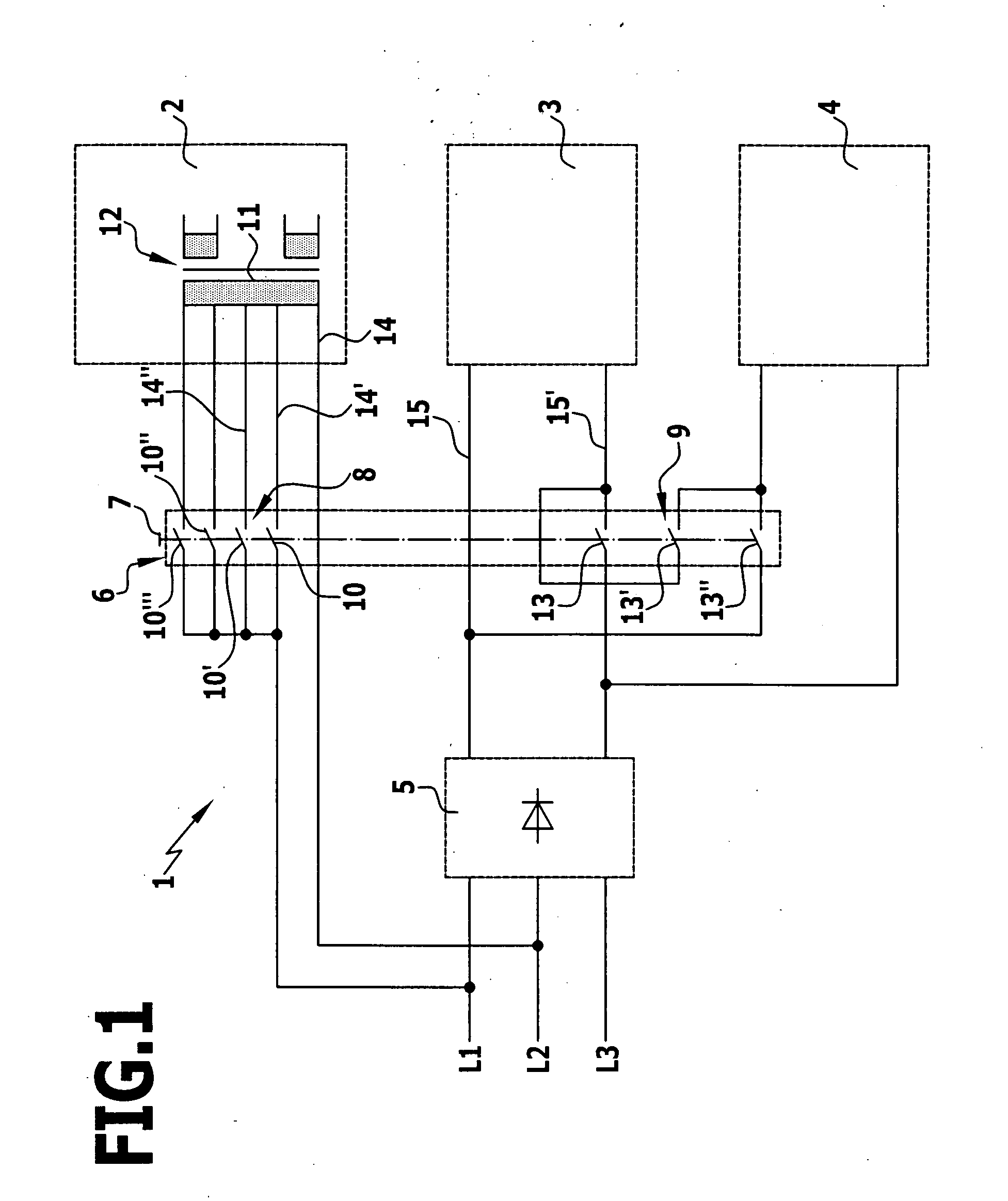
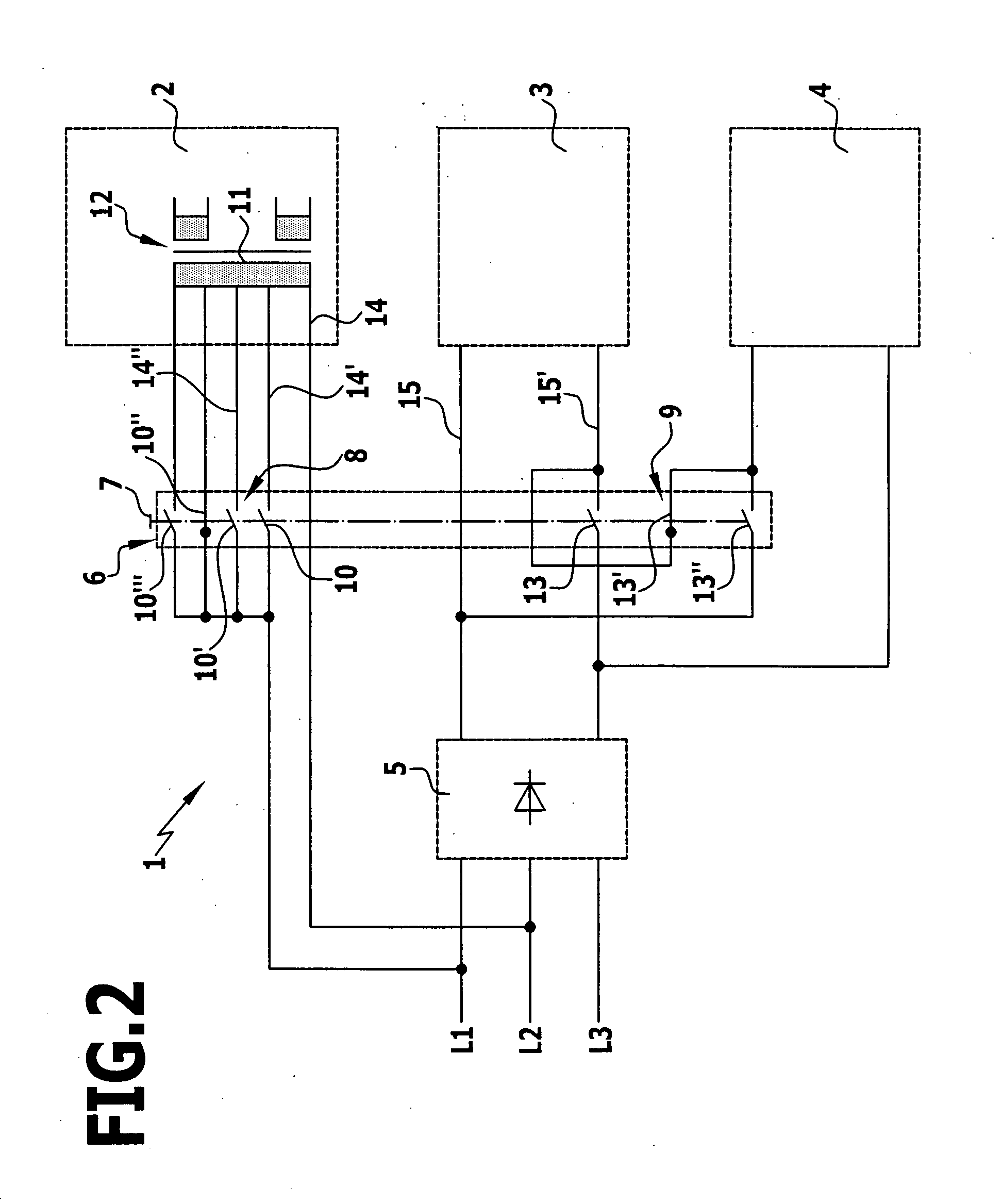
[0016] In accordance with FIG. 1, a welding current source 1 according to the invention comprises a control circuit 2 and two load circuits 3 and 4 for a welding apparatus which is not illustrated. The load circuits 3 and 4 will be referred to hereinbelow as first load circuit 3 and second load circuit 4, respectively. For operating the welding current source 1, a total of three phases L1, L2 and L3 are provided, the two phases L1 and L2 of which lead to the control circuit 2, whereas the two phases L1 and L2 and phase L3 lead to a rectifier 5 connected upstream from the two load circuits 3 and 4. The control circuit 2 is provided for supplying any existing control elements with power, whereas the two load circuits 3 and 4 bear the actual current load during the welding process.

[0017] Since different countries each have country-specific power input voltages, it is desirable to be able to adapt the welding current source 1 as simply and quickly as possible to the respective, country...


PUM

PropertyMeasurementUnit
currentaaaaaaaaaa
voltagesaaaaaaaaaa
electric currentaaaaaaaaaa

Abstract

The present invention relates to a welding current source for a welding apparatus, having inputs for control and load circuits, which are connectable to different electric power networks and are reversibly switchable. The gist of the invention is that a switchover device with first and second switchover mechanisms which are simultaneously actuatable by a common handle is provided, the first switchover mechanism connecting the control circuit to the inputs in a reversibly switchable manner, and the second switchover mechanism connecting the load circuits to the inputs in a reversibly switchable manner.

Description

[0001] The present disclosure relates to the subject matter disclosed in German application number 10 2006 026 020.1 of Jun. 1, 2006, which is incorporated herein by reference in its entirety and for all purposes. BACKGROUND OF THE INVENTION [0002] The invention relates to a welding current source for a welding apparatus, having inputs for control and load circuits, which are connectable to different electric power networks and are reversibly switchable, in accordance with the preamble of claim 1. [0003] Welding current sources generally serve to generate the high current required for the welding. The simplest form of welding current source is a welding transformer, and modern inverter welding apparatus comprise electronic components which first convert the alternating current from the electric power network into direct current, to then transmit it in pulsed form and at a high frequency via the transformer and subsequently rectify and smooth it again. This results, on the one hand, ...

Claims


Application Information

Patent Timeline
Patent Type & Authority Applications(United States)
IPC IPC(8): B23K9/10
CPCB23K9/1068H02M1/10B23K11/243
Inventor DIETERICH, HANSFROEHLICH, OLIVER
Owner LORCH SCHWEISSTECHNIK GMBH
Why Eureka
Try Eureka