Transmitter device, receiver device, transmission method, reception method, and transmitter/receiver device

a technology of transmitter/receiver device and receiver device, which is applied in the direction of selective content distribution, television system, instruments, etc., can solve the problem of loss of compatibility with conventional signals (hereinafter referred to as normal signals)

Active Publication Date: 2013-08-13
SONY CORP
View PDF17 Cites 4 Cited by
  • Summary
  • Abstract
  • Description
  • Claims
  • Application Information

AI Technical Summary

Benefits of technology

[0010]With the aforementioned configuration, it is possible to generate a pre-emphasis signal and switch the receiver device to a state in which the receiver device is capable of performing a process of receiving the pre-emphasis signal only when the receiver device is compatible with the pre-emphasis transmission. Therefore, transmissions of both a pre-emphasis signal and a normal signal are possible.
[0025]As described above, according to the present invention, it is possible to transmit both a pre-emphasis signal, which is obtained by adding to a signal to be transmitted another signal for compensating for the high-frequency components of the signal to be transmitted in advance, and a normal signal, to which such a compensation signal is not added.

Problems solved by technology

However, as the method disclosed in JP 2008-124670A does not support a bandwidth that is wider than the bandwidth increased with the HDMI Ver. 1.3, a further increase in the available bandwidth is desired.
However, the method of adding a signal that compensates for the high-frequency components of a signal to be transmitted has a problem in that the compatibility with the conventional signals (hereinafter referred to as normal signals) could be lost.

Method used


Image

  • Transmitter device, receiver device, transmission method, reception method, and transmitter/receiver device
  • Transmitter device, receiver device, transmission method, reception method, and transmitter/receiver device
  • Transmitter device, receiver device, transmission method, reception method, and transmitter/receiver device

Examples


first embodiment

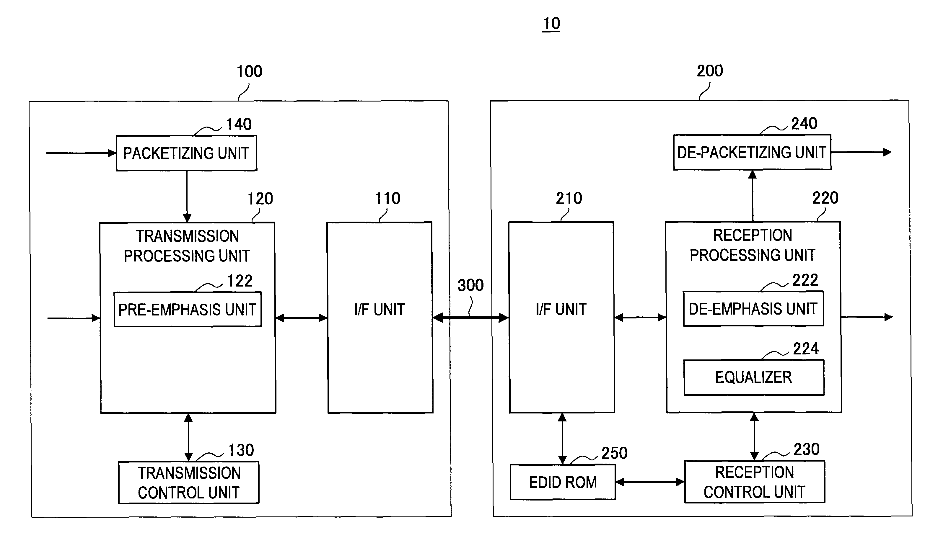
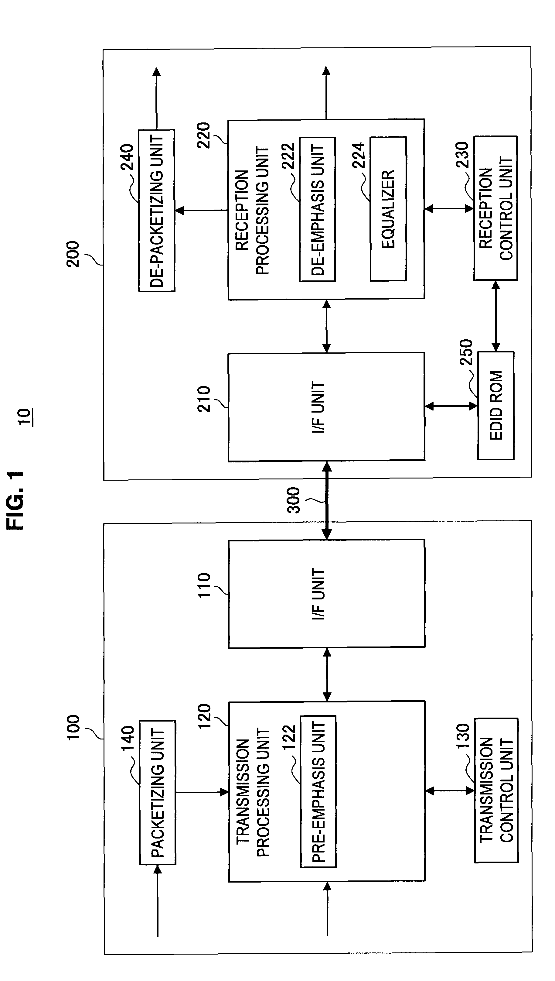
[0089]In the three embodiments of the transmission system 10 described below, control information is transmitted by means of AVI InfoFrame transmitted through a TMDS channel. At this time, the transmitter device 100 determines if the receiver device 200 is compatible with the pre-emphasis transmission on the basis of the EDID information acquired via the DDC line.

[0090]As the acquisition of the EDID information and transmission of the AVI InfoFrame are currently conducted, the first embodiment is advantageous in that it is easy to implement. However, the DDC line and the TMDS line, which are respectively used to acquire the EDID information and transmit the AVI InfoFrame, are only capable of one-way transmission. Therefore, even if control information is transmitted to the receiver device 200 to switch it to the de-emphasis mode corresponding to the pre-emphasis transmission, it would be impossible to check if the operation mode has actually been switched. Therefore, a second embodi...

second embodiment

[0113]Next, the second embodiment in which a CEC control signal is used will be described with reference to FIGS. 8 and 9. As described above, as the CEC line allows two-way communication, the transmitter device 100 can, after having transmitted a control signal for switching the operation mode of the receiver device 200, receive response information from the receiver device 200. The reception control unit 230, upon switching the operation mode of the receiver device 200 to the de-emphasis mode, transmits the response information to the transmitter device 100 via the CEC line. Then, the transmission control unit 130, upon checking the response information, switches the operation mode of the transmitter device 100.

[0114]As shown in FIG. 8, the transmitter device 100 and the receiver device 200 can mutually transmit CEC control signals via the CEC line. As the CEC line allows two-way communication, the receiver device 200 can return response information corresponding to the control in...

third embodiment

[0120]Next, the third embodiment will be described in which the operation mode is switched using packets of the Ethernet (Registered Trademark) through a HEAC, with reference to FIG. 10.

[0121]When the transmitter device 100 and the receiver device 200 are connected via a cable (S404), the transmitter device 100 supplies power to the EDID-ROM in the receiver device 200, and the receiver device 200 returns a HPD signal, whereby the transmitter device 100 detects the HPD (S402). Then, the reception control unit 230 transmits a packet, which indicates information on the reception capability of the receiver device 200, to the transmitter device 100 using the HEAC (S406).

[0122]Then, as in step S108 and step S110 in FIG. 6, the transmission control unit 130 identifies the format of a signal to be transmitted (S408), and determines if the bandwidth should be increased (S410).

[0123]If it is determined that the bandwidth should be increased in step S410, the transmission control unit 130 dete...


PUM


Abstract

There is provided a transmitter device including an interface unit that is an interface for connection to a receiver device via a transmission path, a pre-emphasis unit configured to generate a pre-emphasis signal, the pre-emphasis signal being obtained by adding to an input signal another signal for compensating for a high-frequency component of the input signal, and a transmission control unit configured to acquire identification information indicating whether the receiver device is capable of performing a process of receiving the pre-emphasis signal, switch the receiver device to a state in which the receiver device is capable of performing the process of receiving the pre-emphasis signal in accordance with the identification information, and control the pre-emphasis unit to generate the pre-emphasis signal.

Description

CROSS-REFERENCE TO RELATED APPLICATION[0001]The present application claims priority from Japanese Patent Application No. JP 2010-119134 filed in the Japanese Patent Office on May 25, 2010, the entire content of which is incorporated herein by reference.BACKGROUND OF THE INVENTION[0002]1. Field of the Invention[0003]The present invention relates to a transmitter device, a receiver device, transmission method, a reception method, and a transmitter / receiver device.[0004]2. Description of the Related Art[0005]In recent years, a digital interface standard called HDMI (High Definition Multimedia Interface) has emerged for transmission of video signals and audio signals between devices, and has been widely used in the field of household electrical appliances and AV (Audio and Visual) devices. HDMI has been realized by further developing a DVI (Digital Visual Interface) so that video signals, audio signals, and device control signals can be transmitted over a single cable.[0006]By the way, ...

Claims


Application Information

Patent Timeline
Patent Type & Authority Patents(United States)
IPC IPC(8): G06F3/00G06F13/00
CPCH04B3/143H04N21/43635H04N5/38G06F3/14G09G2370/12G09G2350/00G09G2370/06
Inventor KAWAI, SHIGEHIRO
Owner SONY CORP
Why Eureka
Try Eureka