Longitudinal axial flow drum structure having adjustable threshing diameter

a drum and axial flow technology, applied in the field of grain threshing and separation devices, can solve the problems of increasing labor force, reducing threshing efficiency, and reducing threshing efficiency, so as to improve threshing quality, reduce labor force effectively, and be flexible and convenient and efficient

Active Publication Date: 2022-04-19
JIANGSU UNIV
View PDF17 Cites 0 Cited by
  • Summary
  • Abstract
  • Description
  • Claims
  • Application Information

AI Technical Summary

Benefits of technology

[0004]In order to tackle the failure of real-time and stepless regulation of the threshing diameter when the combine harvester is working, the invention discloses a drum device enabling real-time and stepless regulation of the threshing diameter when the combine harvester is working. Thanks to the invention, the combine harvester has the ability of regulating threshing diameter or threshing gap in real-time and stepless manner when harvesting varieties of grains that are different in moisture content, reaching the optimal threshing work conditions. Hence, it not only enhances grain threshing quality but also saves labor force effectively and lifts operation efficiency of the combine harvester.
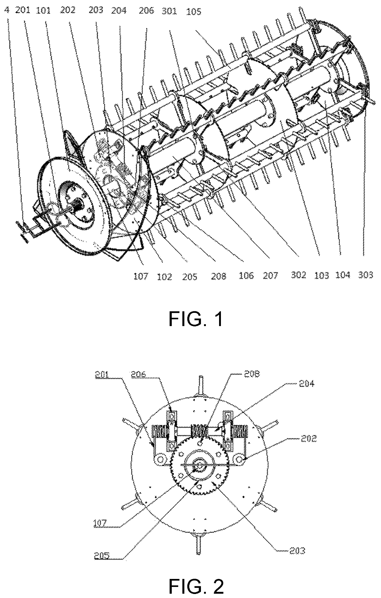
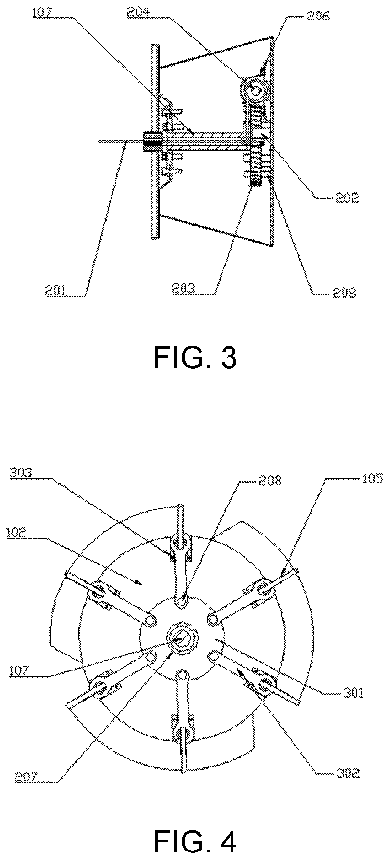
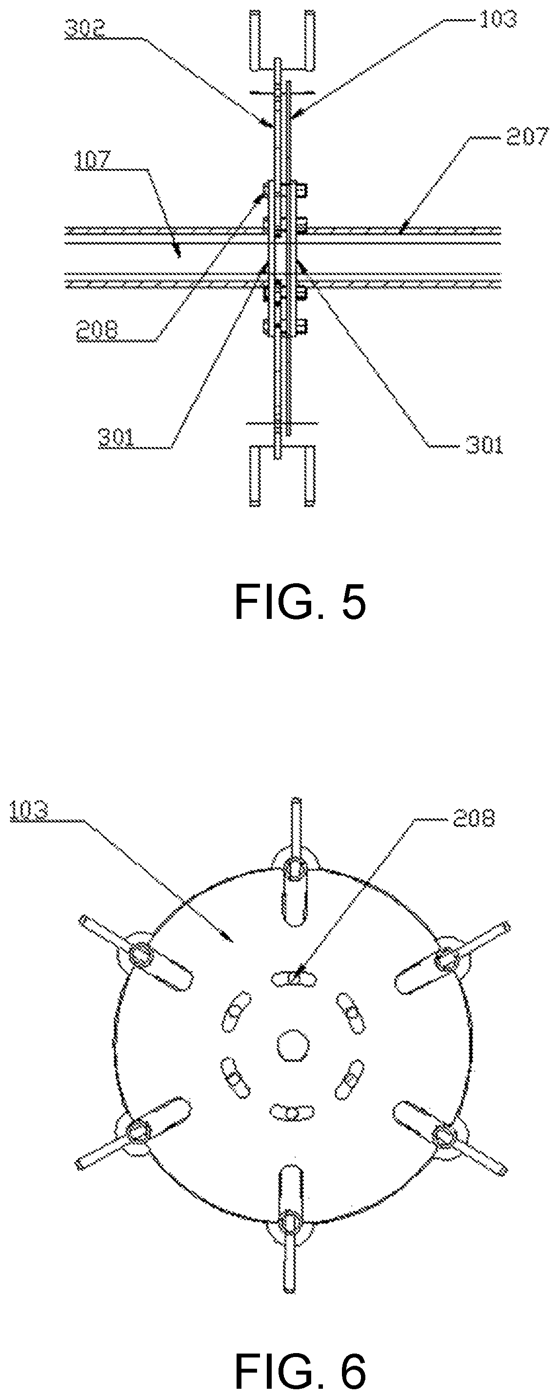
[0016]The transmission mechanism and the diameter regulating mechanism of the longitudinal axial flow drum structure having adjustable threshing diameter as described in the invention rotate along with the front supporting plate, the middle supporting plate and the rear supporting plate under the drive of the drum shaft in threshing process. When it is needed to regulate the threshing drum diameter, the regulating turntable of the diameter regulating mechanism, driven by the transmission mechanism, moves relative to the front supporting plate, the middle supporting plate and the rear supporting plate, driving the motion of the crank linkage. As the moving trajectory of the threshing tooth rod depends on the U-shaped groove in the middle supporting plate, the rod is only able to make rectilinear motion along a radial direction of the threshing drum, namely, sliding up and down in the U-shaped grooves, in order to regulate threshing diameter or threshing gap. To be specific, when the transmission mechanism is configured as a worm and gear mechanism, both regulating steel wires are respectively pulled, and rotation of the worm is driven, so as to drive the worm gear to rotate and to enable rotation of the regulating turntable, thereby realizing real-time and stepless regulation of threshing diameter. When the combine harvester needs to regulate threshing diameter or threshing gap in harvesting varieties of grains that are different in moisture content, the transmission mechanism drives the diameter regulating mechanism to rotate, propelling reciprocating motion of the threshing tooth rod along U-shaped grooves so as to achieve the purpose of real-time and stepless regulation of threshing diameter. Such function enables the threshing gap to conform to the optimal threshing work conditions specific to varieties of grains that are different in moisture, enhancing grain threshing quality. Therefore, the invention is a preferred choice for threshing gap regulation of the threshing and separating device that is installed in the combine harvester.
[0017]The invention has the ability of regulating the threshing diameter in real-time and stepless manner when the combine harvester is working. Compared with the traditional stepped regulation of threshing diameter, the real-time and stepless diameter regulation of the invention, more flexible, convenient and efficient, reduces labor force effectively and enhances fluent operation of the combine harvester.
[0018]In addition, when the transmission mechanism adopts worm and gear design, the helix angle of the worm is less than 5 degrees and the drum is self-locked effectively after regulation of threshing diameter. That is, merely the two regulating steel wires are used to drive rotation of the worm, so as to drive rotation of the worm gear for triggering rotation of the regulating turntable, and the reverse process is disabled. Such feature, good self-locking performance, ensures no rotation of the threshing tooth rod, the regulating turntable and other relevant mechanisms when applied by external force effectively, freeing the threshing tooth rod from uncontrolled looseness and up / down floating motion when the threshing drum is working, which guarantees threshing quality.
[0019]Furthermore, the invention improves trafficability and avoids blockage of materials by controlling the drum threshing diameter. And the installation of the transmission mechanism and the diameter regulating mechanism inside the threshing drum, structurally simple and compact, reduces structural adjustment and occupied space arising from the invention, and cuts down manufacturing cost. Therefore, the invention boasts promising market prospect and competitive power as either axial flow drum or tangential flow is available, contributing to its broad scope of application.
[0020]The connection between or among components or parts features dismountable, such as the connection among the transmission mechanism, the diameter regulating mechanism and the threshing device, and the connection between parts of the transmission mechanism and the diameter regulating mechanism. As a result, such feature of dismountable connection makes possible mutually independent design, production, transport, maintenance and replacement of the parts and components of the product, easy and time-saving assembly and disassembly, and convenient operation, thus greatly cutting down production and use costs of parts and components.

Problems solved by technology

Conversely, the damage rate falls, but the threshing performance worsens.
Therefore, such approach requires longer time and more efforts, leading to low work efficiency.

Method used


Image

  • Longitudinal axial flow drum structure having adjustable threshing diameter
  • Longitudinal axial flow drum structure having adjustable threshing diameter
  • Longitudinal axial flow drum structure having adjustable threshing diameter

Examples


Embodiment Construction

[0030]The invention will be further explained combining with the attached drawings and a specific embodiment in the text below.

[0031]A longitudinal axial flow drum structure having an adjustable threshing diameter as described in the invention comprises a threshing drum, a transmission mechanism and a diameter regulating mechanism. The transmission mechanism delivers power to regulating devices of the diameter regulating mechanism. The diameter regulating mechanism is connected with the transmission mechanism and the threshing drum, to enable threshing diameter regulation. The transmission mechanism and the diameter regulating mechanism are both installed inside the threshing drum.

[0032]As shown in FIG. 1, the diameter regulating mechanism comprises regulating turntable 301s, crank linkages 302 and an adapter sleeve 207. The threshing drum includes a drum shaft 107, and a feeder-beater 101, a front supporting plate 102, a middle supporting plate 103, a rear supporting plate 104 and ...


PUM


Abstract

A longitudinal axial flow drum structure having an adjustable threshing diameter includes a threshing drum, a transmission mechanism, a diameter regulating mechanism and a regulating steel wire pulling mechanism. The transmission mechanism delivers power to regulating devices of the diameter regulating mechanism. The diameter regulating mechanism is connected with the transmission mechanism and the threshing drum to enable threshing diameter regulation. The transmission mechanism and the diameter regulating mechanism are installed inside a feeding cylinder of the threshing drum. The threshing diameter is regulated in real-time and stepless manner by adjusting the regulating steel wire pulling mechanism to pull a regulating steel wire in the transmission mechanism.

Description

CROSS-REFERENCE TO RELATED APPLICATION[0001]This application is a 371 of international application of PCT application serial no. PCT / CN2018 / 080757, filed on Mar. 28, 2018, which claims the priority benefit of China application no. 201810126113.4, filed on Feb. 8, 2018. The entirety of each of the above mentioned patent applications is hereby incorporated by reference herein and made a part of this specification.BACKGROUNDTechnical Field[0002]The invention involves the technical field of the grain threshing and separating device installed in the combine harvester. To be specific, the invention discloses a longitudinal axial flow drum structure having an adjustable threshing diameter.Description of Related Art[0003]As for the combine harvester, the threshing gap exerts great impact on grain threshing quality. In general, the less the threshing gap is, the better the threshing performance gets while the higher the damage rate hits. Conversely, the damage rate falls, but the threshing p...

Claims


Application Information

Patent Timeline
Patent Type & Authority Patents(United States)
IPC IPC(8): A01F12/22A01F7/06A01F12/18
CPCA01F12/22A01F7/06A01F12/181
Inventor LI, YAOMINGSU, ZHANTANG, ZHONG
Owner JIANGSU UNIV
Why Eureka
Try Eureka