Device and method for controlling the start of an internal combustion engine

a technology of control unit and internal combustion engine, which is applied in the direction of engine starters, electric control, ignition automatic control, etc., can solve the problems of incomplete prechamber combustion, insufficient re-activity of the jets, and low starting performance of the engine, so as to improve ignition and combustion of the mixture and reduce particle emissions.

Active Publication Date: 2022-04-26
HITACHI ASTEMO LTD
View PDF16 Cites 0 Cited by
  • Summary
  • Abstract
  • Description
  • Claims
  • Application Information

AI Technical Summary

Benefits of technology

[0035]Summarizing, the control unit and the method for controlling the start of an internal combustion engine equipped with an ignition device including a fuel-fed prechamber significantly reduces the particle emissions during the engine start by performing prechamber heating operation. Due to the increased temperature of the prechamber after heating, wall wetting inside the prechamber can be avoided and reactive flame jets can be generated which lead to an improved ignition and combustion of the mixture in the main combustion chamber during the first main combustion cycle.
[0036]In the following the claimed subject-matter will be further explained based on at least one preferential example with reference to the attached exemplary and schematic drawings.

Problems solved by technology

However, during engine start a prechamber ignition device can cause disadvantages regarding starting performance and emissions since low temperature leads to adverse ignition and combustion conditions inside the prechamber.
As a result, an incomplete prechamber combustion takes place and the re-activity of the jets is not sufficient to ignite the air-fuel mixture in the main combustion chamber completely.
Consequently, the engine either does not start at all or at least produces a high amount of hydrocarbon and particle emissions.
Furthermore, the wall wetting inside the prechamber can lead to fuel deposits therein which may also cause particle emissions.
A high amount of particles at engine start can result in severe problems regarding real driving emissions (RDE) and cold emission tests at −7° C. Especially in hybrid vehicles, at which the internal combustion engine is switched on and off multiple times during the vehicle operation, the particle emissions at engine start play an important role.

Method used


Image

  • Device and method for controlling the start of an internal combustion engine
  • Device and method for controlling the start of an internal combustion engine

Examples


Embodiment Construction

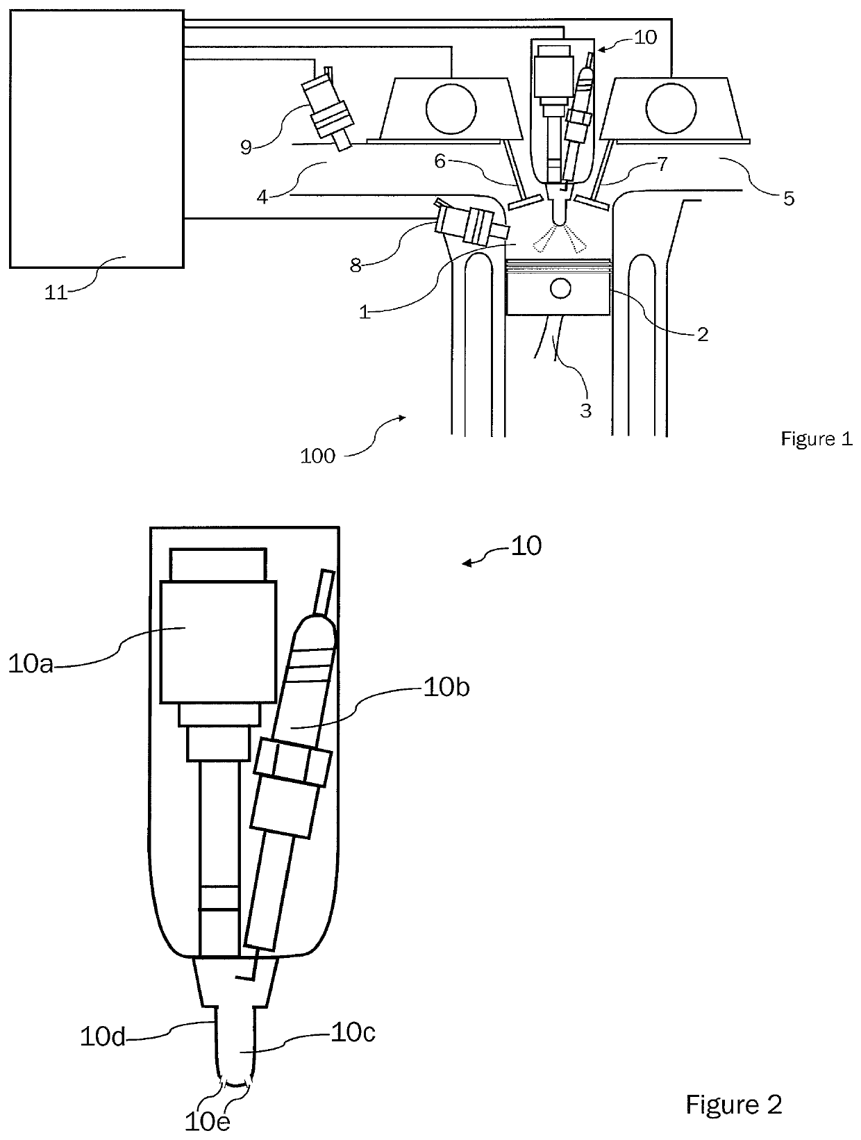
[0041]FIG. 1 shows schematically an exemplary cylinder 100 of an otherwise unspecified internal combustion engine, which may have more than one cylinder 100. The engine may, for example, have two, three, four, six, eight or less / more cylinders 100. The engine comprises at least one piston 2 driven via a connecting rod 3 by a crankshaft (not depicted) for repeated reciprocal movement in the cylinder 100 to define the main combustion chamber therein.

[0042]An (air) intake port 4 with an intake valve 6 as well as an exhaust port 5 with an exhaust valve 7 are connected to the main combustion chamber 1. Ambient air is drawn into the main combustion chamber 1 through the intake port 4. Exhaust gases are discharged from the combustion chamber 1 via the exhaust port 5. An ignition device 10 comprising a spark plug 10a, a prechamber fuel injector 10b and a prechamber 10c is attached to the internal combustion engine.

[0043]The spark plug 10a of the ignition device 10 may be electrically connec...


PUM


Abstract

The present invention relates to a device and a method for controlling the start of an internal combustion engine, wherein the internal combustion engine is equipped with an ignition device comprising a fuel-fed prechamber to ignite an air-fuel mixture in a main combustion chamber. In order to reduce the emissions of the internal combustion engine during engine start a prechamber heating operations is performed by injecting a predetermined amount of fuel into the prechamber and igniting an air-fuel-mixture therein, while the main fuel injector is deactivated during at least a first engine cycle after engine start request.

Description

TECHNICAL FIELD[0001]The present invention relates to a control unit and a method for controlling the start of an internal combustion engine in order to reduce the cold-start emissions, in particular the particle emissions, wherein the internal combustion engine is equipped with an ignition device comprising a fuel-fed prechamber to ignite an air-fuel mixture in a main combustion chamber.BACKGROUND ART[0002]In order to improve the combustion efficiency of an internal combustion engine without drawbacks regarding nitrogen oxide emissions, it is beneficial to combust a very lean air-fuel mixture with an air-fuel ratio λ>2. To ensure a stable ignition and combustion of such an extremely lean mixture, the usage of an ignition device having a fuel-fed prechamber is advantageous. The high ignition energy of such an ignition device is provided by a precombustion taking place in the prechamber. This precombustion is initiated by injecting a small amount of fuel into the prechamber and ig...

Claims


Application Information

Patent Timeline
Patent Type & Authority Patents(United States)
IPC IPC(8): F02D41/00F02D41/06F02B19/12F02P5/15F02B19/18F02N19/02F02D41/40
CPCF02D41/062F02B19/12F02B19/18F02D41/402F02N19/02F02P5/1506F02D41/3094F02D41/064F02D35/025F02B19/1085F02N19/04F02P13/00F02P15/006Y02T10/12F02P5/045
Inventor YONEYA, NAOKISARUWATARI, MASAYUKI
Owner HITACHI ASTEMO LTD
Why Eureka
Try Eureka