
Particle sensor, exhaust system and method for determining particles in the exhaust gas

a technology of particle sensor and exhaust gas, which is applied in the direction of automatic initiation, machines/engines, instruments, etc., can solve the problem that the size of the particles within the exhaust flow cannot be determined with this conventional type of sensor

Inactive Publication Date: 2015-06-09
FORD GLOBAL TECH LLC
View PDF19 Cites 0 Cited by
  • Summary
  • Abstract
  • Description
  • Claims
  • Application Information

AI Technical Summary

Benefits of technology

Enables accurate measurement of particle size distribution, allowing for real-time monitoring of combustion stability and filter effectiveness, enabling adjustments to engine operating parameters to mitigate degraded combustion conditions.

Problems solved by technology

However, the size of the particles within the exhaust flow cannot be determined with this conventional type of sensor.

Method used


Image

  • Particle sensor, exhaust system and method for determining particles in the exhaust gas
  • Particle sensor, exhaust system and method for determining particles in the exhaust gas
  • Particle sensor, exhaust system and method for determining particles in the exhaust gas

Examples


Embodiment Construction

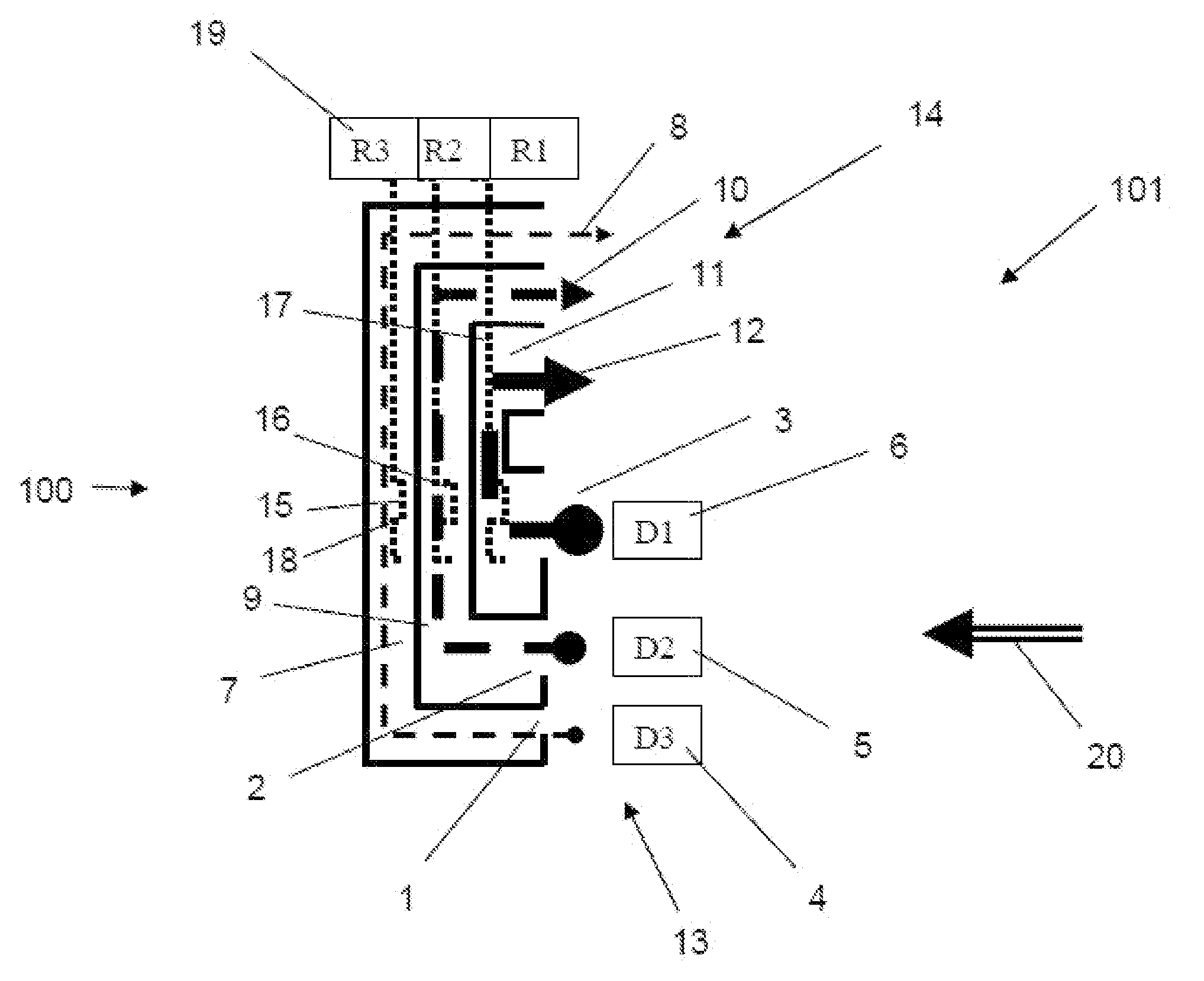
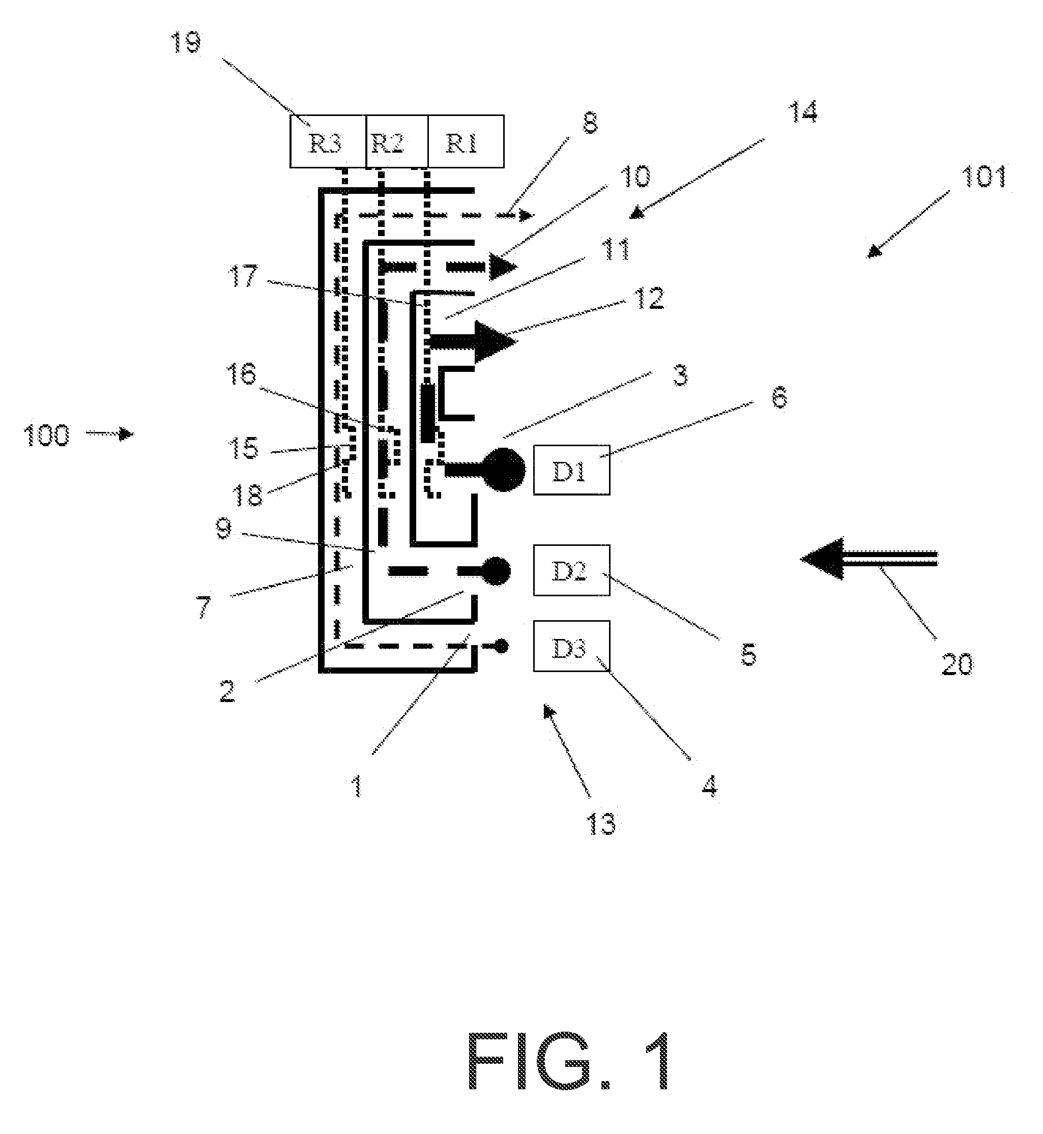
[0014]According to a first aspect of the disclosure, a particle sensor for an exhaust system comprises at least two inlet openings for an exhaust-gas flow of the exhaust system, wherein the inlet openings are of different sizes, and at least two sensor elements, wherein in each case one sensor element is arranged downstream of one inlet opening.

[0015]The particle sensor permits an improved measurement of the particles in the exhaust gas, because it is now possible for measurement to be carried out in a manner differentiated by particle size. It is thus possible for certain particle sizes and also a size distribution to be identified and examined. The specific resistance of a particle sensor with regard to the accumulated particles is also dependent on the size of the particles. The size of the particles which pass to the sensor element is determined by the size and / or shape of the inlet openings. The inlet openings act as a screen or a filter for sorting the particles.

[0016]The sens...


PUM

PropertyMeasurementUnit
temperaturesaaaaaaaaaa
temperatureaaaaaaaaaa
size distributionsaaaaaaaaaa

Abstract

Embodiments of a particle sensor are provided. In one example, a particle sensor for an exhaust system comprises at least two inlet openings for an exhaust-gas flow of the exhaust system, wherein the inlet openings are of different sizes, and at least two sensor elements, wherein in each case one sensor element is arranged downstream of one inlet opening. In this way, the relative proportion of different-sized particles within the exhaust-gas flow may be determined.

Description

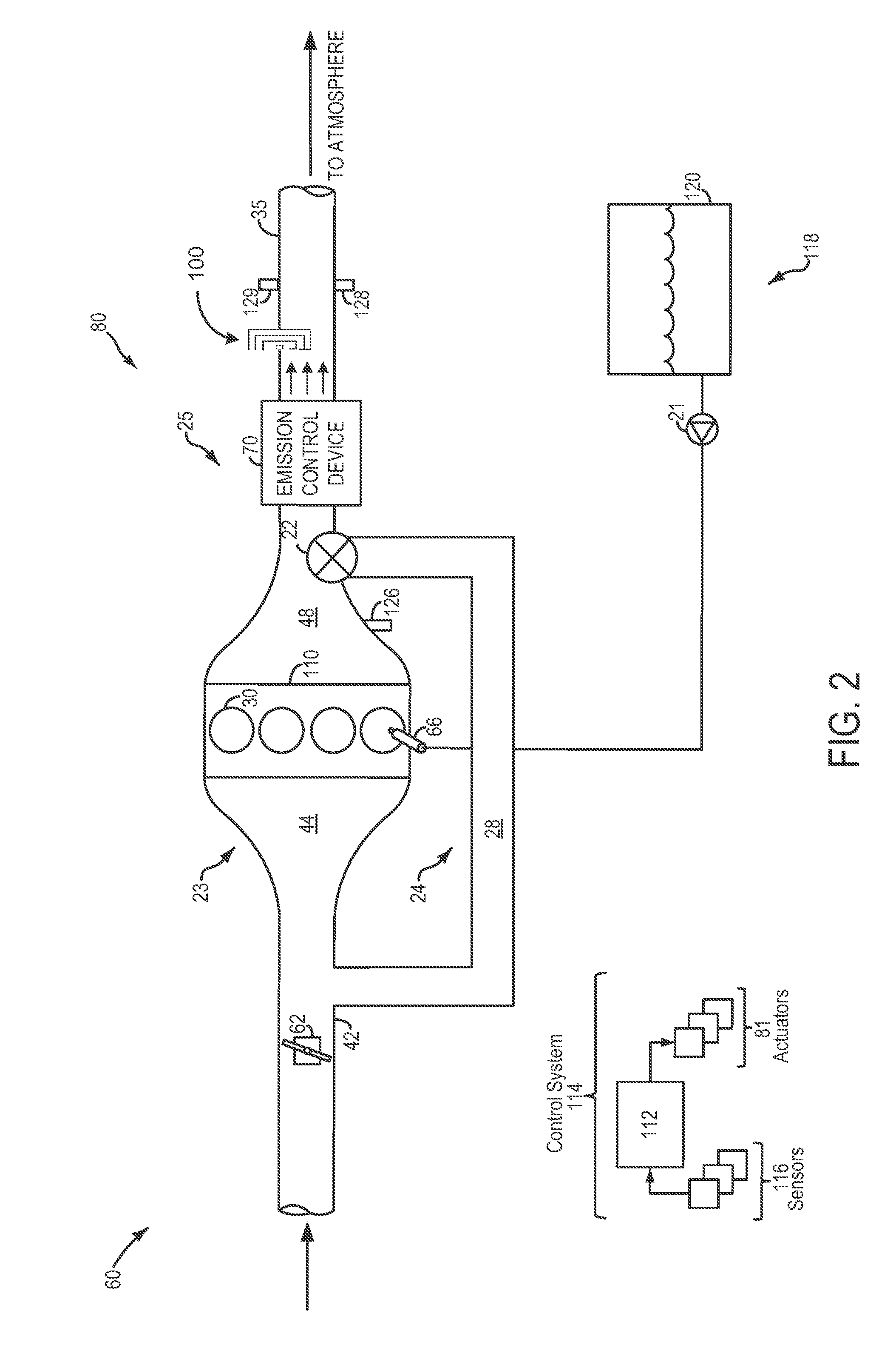
RELATED APPLICATIONS[0001]The present application claims priority to German Patent Application No. 102011002936.2 filed on Jan. 20, 2011, the entire contents of which are hereby incorporated by reference for all purposes.FIELD[0002]The disclosure relates to a particle sensor in an exhaust system.BACKGROUND AND SUMMARY[0003]To reduce the particle emissions of a diesel engine, use is made of soot particle filters. For example, to monitor the effectiveness of said filters, sensors are used which measure the particle content of the exhaust gases flowing through the filter.[0004]At present, resistance particle sensors are known in which two or more metallic electrodes are formed, wherein the particles, in particular soot particles, that are accumulated cause the electrodes, which engage into one another in a comb-like manner, to be short-circuited, and therefore, with increasing particle concentration on the sensor surface, a decreasing resistance or a decreasing impedance (or an increas...

Claims


Application Information

Patent Timeline
Patent Type & Authority Patents(United States)
IPC IPC(8): B60T7/12G01N15/06G01N15/02
CPCG01N15/0656G01N15/0272G01N15/08G01N2015/084
Inventor YACOUB, YASSER MOHAMED SAYEDSCHNEIDER, MATTHEW ALLEN
Owner FORD GLOBAL TECH LLC
Learn More